Visual appearance
The visual appearance of objects is given by the way in which they reflect and transmit light. The color of objects is determined by the parts of the spectrum of (incident white) light that are reflected or transmitted without being absorbed. Additional appearance attributes are based on the directional distribution of reflected (BRDF) or transmitted light (BTDF) described by attributes like glossy, shiny versus dull, matte, clear, turbid, distinct, etc.
Appearance of reflective objects
The appearance of reflecting objects is determined by the way the surface reflects incident light. The reflective properties of the surface can be characterized by a closer look at the (micro)-topography of that surface.
Structures on the surface and the texture of the surface are determined by typical dimensions between some 10 mm and 0.1 mm (the detection limit of the human eye is at ~0.07 mm). Smaller structures and features of the surface cannot be directly detected by the unaided eye, but their effect becomes apparent in objects or images reflected in the surface. Structures at and below 0.1 mm reduce the distinctness of image (DOI), structures in the range of 0.01 mm induce haze and even smaller structures affect the gloss of the surface.
- Definition
diffusion, scattering: process by which the spatial distribution of a beam of radiation is changed in many directions when it is deviated by a surface or by a medium, without change of frequency of its monochromatic components.[1]
- Definition
| Appearance of reflective objects | |
|---|---|
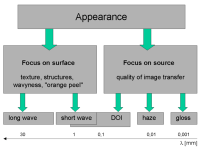 |
Figure 1:Manifestation of surface properties upon reflection of light. Structures with dimensions, λ, above 0,1 mm can be seen directly by the unaided eye (focus on surface), smaller structures become manifest by their effect on the directional distribution of the reflected light (focus on source). Structures at and below 0,1 mm reduce the distinctness of image (DOI), structures in the range of 0,01 mm induce haze and even smaller structures affect the gloss of the surface. |
Basic types of light reflection
 Figure 2A: Specular, mirror like reflection. The inclination of the reflected beam is identical to the inclination of the incident beam. |
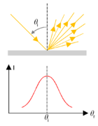 Figure 2B: Reflection haze, the incident light beam is scattered about the specular direction. The intensity of reflection in the specular direction is reduced. |
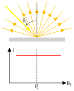 Figure 2C: Ideal (i.e. Lambertian) scattering of the incident beam. The reflected radiant power is constant for all angles of inclination. |
|
| Figures 2: Illustration of the basic types of reflection – specular (mirror like, left), haze (center) and Lambertian diffuse (right). The geometry is shown in the upper part, the intensity versus angle of inclination of a detector is shown in the lower part of the diagrams. | |||
 |
 |
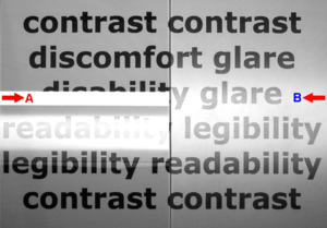
| Figure 3 (left): Light source (fluorescent tube) reflected by a smooth glass surface (left half) and a scattering surface with micro-structures (frosted glass, right half). A distinct image of the lamp is only provided via reflection without scattering.
The scattering of the frosted glass slightly increases the reflected luminance in the areas above and below the position of the lamp (indicated by the arrows). This additional luminance is called haze or veiling glare. |
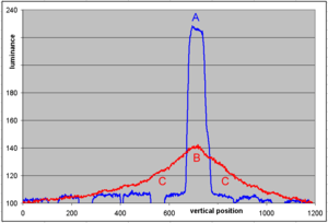
Figure 4 (right): Profile of reflected luminance from the photo in fig. 3 (top to bottom). The scattering of the frosted glass reduces the luminance reflected in the specular direction (A, peaked blue curve vs. B, red curve), but outside the specular direction (at locations C) the luminance is increased by veiling glare. |
Appearance of transmissive objects
| Appearance of transmissive objects | |
|---|---|
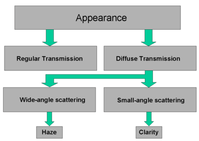 |
Figure 5: Scattering of light during transmission with classification of diffuse transmission into wide and small-angle scattering domains, resulting in haze and reduction of clarity, respectively. |
| Appearance of a Transmissive Object | |
|---|---|
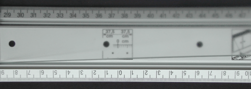 |
Figure 6: graduation of a ruler as seen through a translucent scattering layer (frosted glass). The original distinctness of image can be seen in the center of the lower graduation (around 0). On the left side the frosted glass is in contact with the ruler surface and it is 4 cm above the ruler surface at the right side of the image. With increasing distance between ruler graduation and scattering layer the blur (haze, also see turbidity) increases and the distinctness of image (clarity) decreases. |
Terminology
Reflective objects [2]
- Reflectance factor, R
- Gloss reflectance factor, Rs
- Gloss (at least six types of gloss may be observed depending upon the character of the surface and the spatial (directional) distribution of the reflected light.)
- Specular gloss
- Distinctness of image gloss
- Sheen
- Reflection haze, H (for a specified specular angle), the ratio of (light) flux reflected at a specified angle (or angles) from the specular direction to the flux similarly reflected at the specular angle by a specified gloss standard.[3]
Transmissive objects [4]
- Transmittance, T
- Haze (turbidity)
- Clarity
See also
References
- ↑ CIE No17.4-1987: International lighting vocabulary, 4th ed. (Joint publication IEC/CIE)
- ↑ ASTM Standards on Color & Appearance Measurement
- ↑ ASTM E–430: Standard Test Methods for Measurement of Gloss of High-Gloss Surfaces by Goniophotometry
- ↑ ASTM Standards on Color & Appearance Measurement
- R. S. Hunter, R. W. Harold: The Measurement of Appearance, 2nd Edition, Wiley-IEEE (1987)
- CIE No 38-1977: Radiometric and photometric characteristics of materials and their measurement
- CIE No 44-1979: Absolute methods for reflection measurements
BRDF
- F. E. Nicodemus, et al., Geometric Considerations and Nomenclature for Reflectance, U.S. Dept. of Commerce, NBS Monograph 160 (1977)
- John C. Stover, Optical Scattering, Measurement and Analysis, SPIE Press (1995)