UDOP
The UDOP (UHF Doppler) multistatic radar and multiradar system (MSRS) utilizes Doppler radar for missile tracking and trajectory measurement. A target is illuminated at 450 MHz. Five receiving stations, located along the baselines with the lengths from 40 to 120 km (25 to 75 mi), receive signals from the target's transponder at 900 MHz. These five stations yield slant-range rate. To compute the range or position, an initial position is required from some other tracking system. The random error is 6 cm (2.4 in), but total error includes the systematic error of 2.7 m (8.9 ft) plus the initial error. UDOP had relatively low cost compared with other high-accuracy systems. In the US, MSRS has found important application in the precision measurement of missile trajectories at the Air Force Eastern Test Range, which extends from the Florida mainland to the Indian Ocean. These MSRSs include the AZUSA, the MISTRAM, and the UDOP. All systems employ a cooperative beacon transponder on the observed target and a ground-based transmitting station with several receiving stations at separate, precisely located sites.[1][2]
The UDOP used an AN/DRN-11 transponder installed in the Saturn (rocket family) launch vehicle for Project Gemini missions.
The C-band CW interferometric AZUSA, in operation from the 1950s, has one transmitter and nine receivers located along two crossed baselines with the total lengths of about 500 metres (1,600 ft). Intermediate receivers spaced at 5 to 50 m (16 to 164 ft) are used for phase ambiguity resolution. The AZUSA system measures range by phase measurement of sideband frequencies modulating the carrier, coherent range by Doppler count, two direction cosines, and two cosine rates. Errors of less than 3 m (9.8 ft) in range and 20 ppm in direction cosine are obtainable.[1]
Missile Trajectory Measurement (MISTRAM) is a CW interferometric system with receiving stations situated along two mutually perpendicular baselines spaced at 3 to 30 km (1.9 to 18.6 mi). This MSRS can measure range, four range differences, range rate and four range difference rates of a target. The range error is less than 0.8 m (2.6 ft).[1]
Principles of operation
There is nothing new in using a CW tracking system to obtain metric data. The system was augmented in 1965 by short baselines of a few meters to a few hundred meters in contrast to the conventional UDOP system with baselines of several kilometers and longer. The UDOP system was used extensively for the Saturn program at the NASA John F. Kennedy Space Center (NASA-KSC).[3]
UDOP is a 2-way, coherent, continuous-wave, tracking system. It is a highly reliable data source providing very accurate velocity measurements. The UDOP system, a descendant of Doppler Velocity and Position (DOVAP) was developed by NASA-KSC.
Operation

UDOP consists of three basic elements:
- The ground transmitters
- The airborne transponder
- The ground receiver
In practice, a central recording station and data handling system are also used.
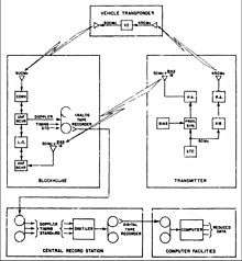
A simplified, functional block diagram of the close-in UDOP tracking system is shown in the figure. The transmitters use a primary frequency standard to derive the frequencies used. The standard is multiplied to 50 MHz and broadcast as a reference signal to the receiver sites. The 50 MHz is multiplied to 450 MHz and transmitted to the transponder on board the vehicle as an interrogation signal. The transponder receives the 450 MHz signal, doubles and re-transmits at 900 MHz.
The ground stations simultaneously receive the 50 MHz reference signal and the 900 MHz transponder signal. The 50 MHz signal is multiplied by 18 and compared to the 900 MHz signal. The difference will be zero for a vehicle on the pad and there will be a doppler effect (measured in cycles per second) if the vehicle is in motion. This effect will be proportional to a loop veiocity with amount depending on the location of the transmitter site, receiver sites, as well as vehicle position and velocity.
The UDOP ground receivers are double, superheterodyne, dual-channel units with common local oscillators. All resulting frequencies after mixing are related to the frequency standard except those experiencing doppler shift. Consequently, the doppler effects are measurable.
Interim-Offset UDOP operation
The existing system operates in an offset mode where the reference frequency is raised to 5 kHz higher than 900 MHz causing a 5 kHz beat frequency as long as the vehicle is on the pad. When the vehicle moves, the doppler effect adds to the 5 kHz frequency. The primary advantage is simplification of data handling as the frequency varies from 5 kHz rather than zero. This offset frequency is derived using phase-locked loop techniques.
Data reduction
The UDOP digitized data recorded from each receiver station was fed to a computer which calculated positions X, Y, and Z. These positions were then fitted to a second degree polynomial using midpoint, moving arc smoothing over a one-second interval. From this process, smoothed position, velocity, and acceleration were obtained.
The data presented were reduced to an earth-fixed, right-handed, rectangular cartesian coordinate system. The Y axis is normal to the Clarke Spheroid of 1866 and positive upward. The X axis is positive in the direction of the flight azimuth. The origin for the UDOP system is at the vehicle transmitting antenna at vehicle launch position.[3]
References
- 1 2 3 V S Chernyak. Fundamentals of Multisite Radar Systems: Multistatic Radars and Multiradar Systems. (Translated from Russian). CRC Press: New York, 1998. pp. 26–27.
- ↑ Schneid, Daniel L. THE UDOP HANDBOOK. National Technical Information Service document no. AD0609038, JUL 1964, 214 pp.
- 1 2 Instrumentation Systems Analysis Branch (K-ED2) and Tracking Branch (K-EF4), Saturn early launch phase tracking by CW Doppler, John F. Kennedy Space Center, SP-79, April 13, 1964, NASA doc. no. N65-19700, 52 pp.