Screw terminal

A screw terminal is a type of electrical connector where a wire is held by the tightening of a screw.
Description
The wire may be wrapped directly under the head of a screw, may be held by a metal plate forced against the wire by a screw, or may be held by what is, in effect, a set screw in the side of a metal tube. The wire may be directly stripped of insulation and inserted under the head of a screw or into the terminal. Otherwise, it may be either inserted first into a ferrule, which is then inserted into the terminal, or else attached to a connecting lug. which is then fixed under the screw head.
Depending on the design, a flat-blade screwdriver, a cross-blade screwdriver, hex key, Torx key, or other tool may be required to properly tighten the connection for reliable operation.
Applications
Screw terminals are used extensively in building wiring for the distribution of electricity - connecting electrical outlets, luminaires and switches to the mains, and for directly connecting major appliances such as clothes dryers and ovens drawing in excess of 15 amperes.
Screw terminals are commonly used to connect a chassis ground, such as on a record player or surge protector. Most public address systems in buildings also use them for speakers, and sometimes for other outputs and inputs. Alarm systems and building sensor and control systems have traditionally used large numbers of screw terminations.
Grounding screws are often color-coded green and, when used on consumer electronics, often have a washer with gripping "teeth".
Printed circuit board (PCB) terminal blocks are specially designed with a copper alloy pin of suitable size and length and can be inserted in printed circuit boards to be soldered to allow electrical signals and current to flow to and from PCBs and electrical equipment. Some designs provide features that allow the flow of molten solder to endure a better connection between the circuit traces of the board and the electrical equipment which is meant to be controlled or fed appropriate power.
Multiway versions

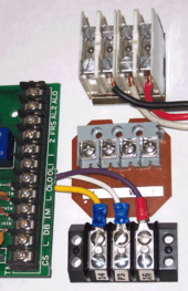
Multiple screw terminals can be arranged in the form of a barrier strip (as illustrated at the top right), with a number of short metal strips separated by a raised insulated "barrier" on an insulating "block" - each strip having a pair of screws with each screw connecting to a separate conductor, one at each end of the strip. These are known as connector strips or chocolate blocks ("choc blocks") in the UK. This nick-name arises from the first such connectors made in the UK by GEC, Witton in the 1950s. Moulded in brown plastic they were said to resemble a small bar of chocolate.
A similar arrangement is common with paired screw terminals, where metal tubes are loosely encased in an insulating block with a set screw at each end of each tube to hold and thus connect a conductor. These are often used to connect light fixtures and are shown at the right.
Alternatively, terminals can also be arranged as a terminal strip or terminal block, with several screws along (typically) two long strips. This creates a bus bar for power distribution, and so may also include a master input connector, usually binding posts or banana connectors.
Installation
Assembly of a screw connection requires some care in workmanship to ensure proper removal of insulation, containment of all wire strands, and the adequate tightening of the screw. If the wire diameter is small in relation to the size of the screw, the wire may be cut through by the over-tightening of the screw. This is less likely to occur when a wire is clamped between two plates by the action of a screw. Since wire strands may not be contained by the screw head in a basic screw terminal, stranded wires may be crimped into a ferrule to prevent the bridging of terminals; this partly offsets the economy of a "bare" wire termination.
While wires may be crimped, they should not be heavily tinned with solder prior to installation in a screw terminal, since the soft metal will cold flow, resulting in a loose connection and possible fire hazard. Screw connectors sometimes come loose if not done up tightly enough at fitting time. Verifying adequate tightening torque requires calibrated installation tools and proper training. In the UK, all screw connectors on fixed mains installations are required to be accessible for servicing, for this reason.
Advantages and disadvantages

Screw terminals are low in cost when compared to other types of connectors, and can be readily designed into products for circuits carrying currents of from a fraction of an ampere up to several hundred amperes at low to moderate frequencies. The terminals easily can be re-used in the field, allowing for the replacement of wires or equipment, generally with standard hand tools. Screw terminals usually avoid the requirement for a specialized mating connector to be applied to the ends of wires.
When properly tightened, the connections are physically and electrically secure because they firmly contact a large section of wire. The terminals are relatively low cost compared with other types of connector, and a screw terminal can easily be integrated into the design of a building wiring device (such as a socket, switch, or lamp holder).
Disadvantages include the time taken to strip a wire and, in basic terminals, properly wrap it around a screw head, since it is essential that any wire installed under a screw head be "wound" in the correct direction (usually clockwise,) so that the conductors are not forced outwards when the screw is tightened. This procedure is more time consuming than using a plug-in connector - thus making screw connections uncommon for portable equipment, where wires are repeatedly connected and disconnected.
However, with the clamping plate type of screw terminal this time is reduced, since it is necessary only to insert the stripped wire between the terminal and the rear clamping plate then tighten the connection, using the screw to clamp the wire between the terminal and the clamping plate, without any need properly to wrap it around the screw head.
The screw mechanism limits the minimum physical size of a terminal, making screw terminals less useful where very many connections are required.
It is difficult to automate multiple terminations with screw connections.
Vibration or corrosion can cause a screw connection to deteriorate over time.
History

Screw terminals were one of the first types of electrical connectors to be used, with one of the earliest patents found utilizing a screw "terminal" being that awarded to William P. Marr of Toronto, Canada - for an "Electric Wire Connecter" U.S. Patent 1,583,479, Filed March 3 1923, Patented May 4,1926[1]