Shading

Shading refers to depicting depth perception in 3D models or illustrations by varying levels of darkness.

Drawing

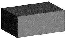
Shading is used in drawing for depicting levels of darkness on paper by applying media more densely or with a darker shade for darker areas, and less densely or with a lighter shade for lighter areas. There are various techniques of shading including cross hatching where perpendicular lines of varying closeness are drawn in a grid pattern to shade an area. The closer the lines are together, the darker the area appears. Likewise, the farther apart the lines are, the lighter the area appears.
Light patterns, such as objects having light and shaded areas, help when creating the illusion of depth on paper.[1][2]
Powder shading is a sketching shading method. In this style, the stumping powder and paper stumps are used to draw a picture. This can be in color. The stumping powder is smooth and doesn't have any shiny particles. The paper to be used should have small grains on it so that the powder remains on the paper.
Computer graphics
In computer graphics, shading refers to the process of altering the color of an object/surface/polygon in the 3D scene, based on things like (but not limited to) the surface's angle to lights, its distance from lights, its angle to the camera and material properties (e.g. bidirectional reflectance distribution function) to create a photorealistic effect. Shading is performed during the rendering process by a program called a shader.
Angle to light source
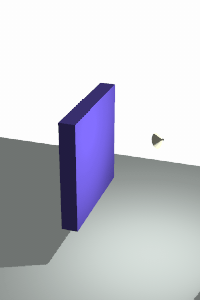
Shading alters the colors of faces in a 3D model based on the angle of the surface to a light source or light sources.
The first image below has the faces of the box rendered, but all in the same color. Edge lines have been rendered here as well which makes the image easier to see.
The second image is the same model rendered without edge lines. It is difficult to tell where one face of the box ends and the next begins.
The third image has shading enabled, which makes the image more realistic and makes it easier to see which face is which.
 |
 |
Lighting

Shading is also dependent on the lighting used. Usually, upon rendering a scene a number of different lighting techniques will be used to make the rendering look more realistic. Different types of light sources are used to give different effects.
Ambient lighting
An ambient light source represents an omni-directional, fixed-intensity and fixed-color light source that affects all objects in the scene equally. Upon rendering, all objects in the scene are brightened with the specified intensity and color. This type of light source is mainly used to provide the scene with a basic view of the different objects in it. This is the simplest type of lighting to implement and models how light can be scattered or reflected many times producing a uniform effect.
Ambient lighting can be combined with ambient occlusion to represent how exposed each point of the scene is, affecting the amount of ambient light it can reflect. This produces diffuse, non-directional lighting throughout the scene, casting no clear shadows, but with enclosed and sheltered areas darkened. The result is usually visually similar to an overcast day.
Directional lighting
A directional light source illuminates all objects equally from a given direction, like an area light of infinite size and infinite distance from the scene; there is shading, but cannot be any distance falloff.
Point lighting
Light originates from a single point, and spreads outward in all directions.
Spotlight lighting
Models a Spotlight. Light originates from a single point, and spreads outward in a cone.
Area lighting
Light originates from a small area on a single plane. A more realistic model than a point light source.
Volumetric lighting
Light originating from a small volume, an enclosed space lighting objects within that space.
Shading is interpolated based on how the angle of these light sources reach the objects within a scene. Of course, these light sources can be and often are combined in a scene. The renderer then interpolates how these lights must be combined, and produces a 2d image to be displayed on the screen accordingly.
Distance falloff
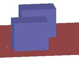
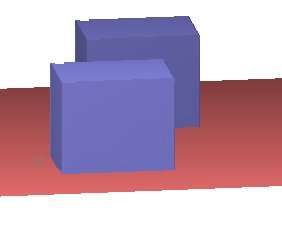
Theoretically, two surfaces which are parallel are illuminated the same amount from a distant light source, such as the sun. Even though one surface is further away, your eye sees more of it in the same space, so the illumination appears the same.
The left image doesn't use distance falloff. Notice that the colors on the front faces of the two boxes are exactly the same. It appears that there is a slight difference where the two faces meet, but this is an optical illusion caused by the vertical edge below where the two faces meet.
The right image uses distance falloff. Notice that the front face of the front box is brighter than the front face of the back box. Also, the floor goes from light to dark as it gets farther away.
This distance falloff effect produces images which appear more realistic.
 Two boxes rendered with an OpenGL renderer.
Note that the colors of the two front faces are the same even though one box is farther away. |
 The same model rendered using ARRIS CAD which implements "Distance Falloff" to make surfaces that are closer to the eye appear brighter. |
Distance falloff can be calculated in a number of ways:
- Power of the distance – For a given point at a distance x from the light source, the light intensity received is proportional to 1/xn.
- None (n = 0) – The light intensity received is the same regardless of the distance between the point and the light source.
- Linear (n = 1) – For a given point at a distance x from the light source, the light intensity received is proportional to 1/x.
- Quadratic (n = 2) – This is how light intensity decreases in reality if the light has a free path (i.e. no fog or any other thing in the air that can absorb or scatter the light). For a given point at a distance x from the light source, the light intensity received is proportional to 1/x2.
- Any number of other mathematical functions may also be used.
Interpolation techniques
When calculating the brightness of a surface during rendering, our illumination model requires that we know the surface normal. However, a 3D model is usually described by a polygon mesh, which may only store the surface normal at a limited number of points, usually either in the vertices, in the polygon faces, or in both. To get around this problem, one of a number of interpolation techniques can be used.
Flat shading
Here, a color is calculated for one point on each polygon (usually for the first vertex in the polygon, but sometimes for the centroid for triangle meshes), based on the polygon's surface normal and on the assumption that all polygons are flat. The color everywhere else is then interpolated by coloring all points on a polygon the same as the point for which the color was calculated, giving each polygon a uniform color (similar to in nearest-neighbor interpolation). It is usually used for high speed rendering where more advanced shading techniques are too computationally expensive. As a result of flat shading all of the polygon's vertices are colored with one color, allowing differentiation between adjacent polygons. Specular highlights are rendered poorly with flat shading: If there happens to be a large specular component at the representative vertex, that brightness is drawn uniformly over the entire face. If a specular highlight doesn’t fall on the representative point, it is missed entirely. Consequently, the specular reflection component is usually not included in flat shading computation.
Smooth shading
In contrast to flat shading where the colors change discontinuously at polygon borders, with smooth shading the color changes from pixel to pixel, resulting in a smooth color transition between two adjacent polygons. Usually, values are first calculated in the vertices and bilinear interpolation is then used to calculate the values of pixels between the vertices of the polygons.
Types of smooth shading include:
Gouraud shading
- Determine the normal at each polygon vertex.
- Apply an illumination model to each vertex to calculate the light intensity from the vertex normal.
- Interpolate the vertex intensities using bilinear interpolation over the surface polygon.
Data structures
- Sometimes vertex normals can be computed directly (e.g. height field with uniform mesh)
- More generally, need data structure for mesh
- Key: which polygons meet at each vertex.
Advantages
- Polygons, more complex than triangles, can also have different colors specified for each vertex. In these instances, the underlying logic for shading can become more intricate.
Problems
- Even the smoothness introduced by Gouraud shading may not prevent the appearance of the shading differences between adjacent polygons.
- Gouraud shading is more CPU intensive and can become a problem when rendering real time environments with many polygons.
- T-Junctions with adjoining polygons can sometimes result in visual anomalies. In general, T-Junctions should be avoided.
Phong shading
Phong shading is similar to Gouraud shading, except that instead of interpolating the light intensities, the normals are interpolated between the vertices. Thus, the specular highlights are computed much more precisely than in the Gouraud shading model:
- Compute a normal N for each vertex of the polygon.
- From bilinear interpolation compute a normal, Ni, for each pixel. (This must be renormalized each time.)
- Apply an illumination model to each pixel to calculate the light intensity from Ni.
Other Approaches
Both Gouraud shading and Phong shading can be implemented using bilinear interpolation. Bishop and Weimer [5] proposed to use a Taylor series expansion of the resulting expression from applying an illumination model and bilinear interpolation of the normals. Hence, second degree polynomial interpolation was used. This type of biquadratic interpolation was further elaborated by Barrera et al.,[6] where one second order polynomial was used to interpolate the diffuse light of the Phong reflection model and another second order polynomial was used for the specular light.
Spherical Linear Interpolation (Slerp) was used by Kuij and Blake [7] for computing both the normal over the polygon as well as the vector in the direction to the light source. A similar approach was proposed by Hast,[8] which uses Quaternion interpolation of the normals with the advantage that the normal will always have unit length and the computationally heavy normalization is avoided.
Flat vs. smooth shading
| Flat | Smooth |
|---|---|
| Uses the same color for every pixel in a face – usually the color of the first vertex | Smooth shading uses linear interpolation of either colors or normals between vertices |
| Edges appear more pronounced than they would on a real object because in reality almost all edges are somewhat round | The edges disappear with this technique |
| Same color for any point of the face | Each point of the face has its own color |
| Individual faces are visualized | Visualize underlying surface |
| Not suitable for smooth objects | Suitable for any objects |
| Less computationally expensive | More computationally expensive |
See also
References
- ↑ "Drawing Techniques". Drawing With Confidence. Retrieved 19 September 2012.
- ↑ "Shading Tutorial, How to Shade in Drawing". Dueysdrawings.com. 2007-06-21. Retrieved 2012-02-11.
- ↑ Gouraud, Henri (1971). "Continuous shading of curved surfaces". IEEE Transactions on Computers. C–20 (6): 623–629. doi:10.1109/T-C.1971.223313.
- ↑ B. T. Phong, Illumination for computer generated pictures, Communications of ACM 18 (1975), no. 6, 311–317.
- ↑ Gary Bishop and David M. Weimer. 1986. Fast Phong shading. SIGGRAPH Comput. Graph. 20, 4 (August 1986), 103-106.
- ↑ T. Barrera, A. Hast, E. Bengtsson. Fast Near Phong-Quality Software Shading. WSCG'06, pp. 109-116. 2006
- ↑ Kuijk, A. A. M. and E. H. Blake, Faster Phong shading via angular interpolation. Computer Graphics Forum 8(4):315-324. 1989
- ↑ A. Hast. Shading by Quaternion Interpolation. WSCG'05. pp. 53-56. 2005.
