Immunity-aware programming
When writing firmware for an embedded system, immunity-aware programming refers to programming techniques which improve the tolerance of transient errors in the program counter or other modules of a program that would otherwise lead to failure. Transient errors are typically caused by single event upsets, insufficient power, or by strong electromagnetic signals transmitted by some other "source" device.
Immunity-aware programming is an example of defensive programming and EMC-aware programming. Although most of these techniques apply to the software in the "victim" device to make it more reliable, a few of these techniques apply to software in the "source" device to make it emit less unwanted noise.
Task and objectives
Microcontrollers' firmware can inexpensively improve the electromagnetic compatibility of an embedded system.
Embedded systems firmware is usually not considered to be a source of radio frequency interference. Radio emissions are often caused by harmonic frequencies of the system clock and switching currents. The pulses on these wires can have fast rise and fall times, causing their wires to act as radio transmitters. This effect is increased by badly-designed printed circuit boards. These effects are reduced by using microcontroller output drivers with slower rise times, or by turning off system components.
The microcontroller is easy to control. It is also susceptible to faults from radio frequency interference. Therefore, making the microcontroller's software resist such errors can cheaply improve the system's tolerance for electromagnetic interference by reducing the need for hardware alterations.
Possible interferences of microcontroller-based systems
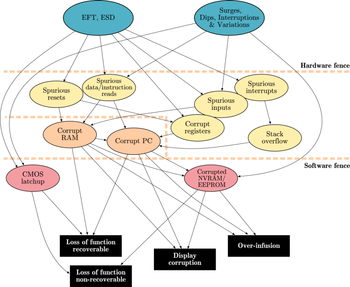
CMOS microcontrollers have specific weak spots which can be strengthened by software that works against electromagnetic interference. Failure mode and effects analysis of a system and its requirements is often required. Electromagnetic compatibility issues can easily be added to such an analysis.
Power supply
Slow changes of power supply voltage do not cause significant disturbances, but rapid changes can make unpredictable trouble. If a voltage exceeds parameters in the controller's data sheet by 150 percent, it can cause the input port or the output port to get hung in one state, known as CMOS latch-up.[1] Without internal current control, latch-up causes the microcontroller to burn out. The standard solution is a mix of software and hardware changes. Most embedded systems have a watchdog timer. This watchdog should be external to the microcontroller so that it is likely to be immune to any plausible electromagnetic interference. It should reset the power supply, briefly switching it off. The watchdog period should be half or less of the time and power required to burn out the microcontroller. The power supply design should be well-grounded and decoupled using capacitors and inductors close to the microcontroller; some typical values are 100uF and 0.1uF in parallel.
Low power can cause serious malfunctions in most microcontrollers. For the CPU to successfully decode and execute instructions, the supplied voltage must not drop below the minimum voltage level. When the supplied voltage drops below this level, the CPU may start to execute some instructions incorrectly. The result is unexpected activity on the internal data and control lines. This activity may cause:
- CPU register corruption
- I/O register corruption
- I/O pin random toggling
- SRAM corruption
- EEPROM corruption
Brownout detection solves most of those problems in most systems by causing the system to shut down when mains power is unreliable. One typical system retriggers a timer each time that the AC main voltage exceeds 90% of its rated voltage. If the timer expires, it interrupts the microcontroller, which then shuts down its system. Many systems also measure the power supply voltages, to guard against slow power supply degradation.
The oscillator
The input ports of CMOS oscillators have high impedances, and are thus very susceptible to transient disturbances. According to Ohm's law, high impedance causes high voltage differences. They also are very sensitive to short circuit from moisture or dust.
One typical failure is when the oscillators' stability is affected. This can cause it to stop, or change its period. The normal system hedges are to have an auxiliary oscillator using some cheap, robust scheme such as a ring of inverters or a resistor-capacitor one-shot timer. After a reset (perhaps caused by a watchdog timer), the system may default to these, only switching in the sensitive crystal oscillator once timing measurements have proven it to be stable. It is also common in high-reliability systems to measure the clock frequency by comparing it to an external standard, usually a communications clock, the power line, or a resistor-capacitor timer.
Bursts of electromagnetic interference can shorten clock periods or cause runt pulses that lead to incorrect data access or command execution. The result is wrong memory content or program pointers. The standard method of overcoming this in hardware is to use an on-chip phase locked loop to generate the microcontroller's actual clock signal. Software can periodically verify data structures and read critical ports using voting, distributing the reads in time or space.
Input/output ports
Input/output ports—including address lines and data lines—connected by long lines or external peripherals are the antennae that permit disturbances to have effects. Electromagnetic interference can lead to incorrect data and addresses on these lines. Strong fluctuations can cause the computer to misread I/O registers or even stop communication with these ports. Electrostatic discharge can actually destroy ports or cause malfunctions.
Most microcontrollers' pins are high impedance inputs or mixed inputs and outputs. High impedance input pins are sensitive to noise, and can register false levels if not properly terminated. Pins that are not terminated inside an IC need resistors attached. These have to be connected to ground or supply, ensuring a known logic state.

Corrective actions
An analysis of possible errors before correction is very important. The cause must be determined so that the problem can be fixed.
The Motor Industry Software Reliability Association identifies the required steps in case of an error as follows:[2]
- Information/warning the user
- Store the faulty data until a defined reset can be carried out
- Keep the system in a defined state until the error can be corrected
Fundamentally one uses redundancy to counter faults. This includes running extra code (redundancy in time) as well as keeping extra bits (redundancy in space).
Instruction pointer (IP) error management
A disturbed instruction pointer can lead to serious errors, such as an undefined jump to an arbitrary point in the memory, where illegal instructions are read. The state of the system will be undefined. IP errors can be handled by use of software based solutions such as function tokens and an NOP slide(s).
Many processors, such as the Motorola 680x0, feature a hardware trap upon encountering an illegal instruction. A correct instruction, defined in the trap vector, is executed, rather than the random one. Traps can handle a larger range errors than function tokens and NOP slides. Supplementary to illegal instructions, hardware traps securely handle memory access violations, overflows, or a division by zero.
Token passing (function token)


Improved noise immunity can be achieved by execution flow control known as token passing. The figure to the right shows the functional principle schematically. This method deals with program flow errors caused by the instruction pointers.
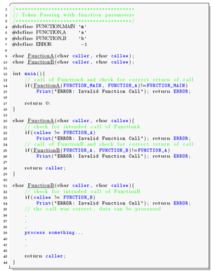
The implementation is simple and efficient. Every function is tagged with a unique function ID. When the function is called, the function ID is saved in a global variable. The function is only executed if the function ID in the global variable and the ID of the function match. If the IDs do not match, an instruction pointer error has occurred, and specific corrective actions can be taken. A sample implementation of token passing using a global variable programmed in C is stated in the following source listing.
This is essentially an "arm / fire" sequencing, for every function call. Requiring such a sequence is part of safe programming techniques, as it generates tolerance for single bit (or in this case, stray instruction pointer) faults.
The implementation of function tokens increases the program code size by 10 to 20%, and slows down the performance. To improve the implementation, instead of global variables like above, the function ID can be passed as an argument within the functions header as shown in the code sample below.

NOP slide
With NOP-Fills, the reliability of a system in case of a disturbed instruction pointer can be improved in some cases. The entire program memory that is not used by the program code is filled with No-Operation (NOP) instructions. In machine code a NOP instruction is often represented by 0x00 (for example, Intel 8051, ATmega16, etc.). The system is kept in a defined state. At the end of the physical program memory, an instruction pointer error handling (IPEH IP-Error-Handler) has to be implemented. In some cases this can be a simple reset.
If an instruction pointer error occurs during the execution and a program points to a memory segment filled with NOP instructions, inevitably an error occurred and is recognized.
Three methods of implementing NOP-Fills are applicable:
- In the first method, the unused physical memory is set to 0x00 manually by search and replace in the (HEX) program file. The drawback of this method is that this has to be done after every compilation.

- The second method uses the fill option of the linker, which fills up the unused memory regions with a predefined constant (in this case 0x00).
- The third way is to include a corresponding number of NOP assembler directives directly in the program code.
When using the CodevisionAVR C compiler, NOP fills can be implemented easily. The chip programmer offers the feature of editing the program flash and EEPROM to fill it with a specific value. Using an Atmel ATmega16, no jump to reset address 0x00 needs to be implemented, as the overflow of the instruction pointer automatically sets its value to 0x00. Unfortunately, resets due to overflow are not equivalent to intentional reset. During the intended reset, all necessary MC registers are reset by hardware, which is not done by a jump to 0x00. So this method will not be applied in the following tests.

I/O register errors
Microcontroller architecture requires the I/O leads to be placed at the outer edge of the silicon die. Thus I/O contacts are strongly affected by transient disturbances on their way to the silicon core, and I/O registers are one of the most vulnerable parts of the microcontroller. Wrongly-read I/O registers may lead to an incorrect system state. The most serious errors can occur at the reset port and interrupt input ports. Disturbed data direction registers (DDR) may inhibit writing to the bus.
These disturbances can be prevented as following:
1. Cyclic update of the most important registers
- By cyclically updating of the most important register and the data in the data direction registers in shortest possible intervals, errors can be reduced. Thus a wrongly set bit can be corrected before it can have negative effects.
2. Multiple read of input registers
- A further method of filtering disturbances is multiple read of input registers. The read-in values are then checked for consistency. If the values are consistent, they can be considered valid. A definition of a value range and/or the calculation of a mean value can improve the results for some applications.
- Side effect: increased activity
- A drawback is the increased activity due to permanent updates and readouts of peripherals. This activity may add additional emissions and failures.
- External interrupt ports; stack overflow
- External interrupts are triggered by falling/rising edges or high/low potential at the interrupt port, leading to an interrupt request (IRQ) in the controller. Hardware interrupts are divided into maskable interrupts and non-maskable interrupts (NMI). The triggering of maskable interrupts can be stopped in some time-critical functions. If an interrupt is called, the current instruction pointer (IP) is saved on the stack, and the stack pointer (SP) is decremented. The address of the interrupt service routine (ISR) is read from the interrupt vector table and loaded to the IP register, and the ISR is executed as a consequence.
- If interrupts—due to disturbances—are generated faster than processed, the stack grows until all memory is used. Data on the stack or other data might be overwritten. A defensive software strategy can be applied. The stack pointer (SP) can be watched. The growing of the stack beyond a defined address can then be stopped. The value of the stack pointer can be checked at the start of the interrupt service routine. If the SP points to an address outside the defined stack limits, a reset can be executed.
Data redundancy
In systems without error detection and correction units, the reliability of the system can be improved by providing protection through software. Protecting the entire memory (code and data) may not be practical in software, as it causes an unacceptable amount of overhead, but it is a software implemented low-cost solution for code segments.
Another elementary requirement of digital systems is the faultless transmission of data. Communication with other components can be the weak point and a source of errors of a system. A well-thought-out transmission protocol is very important. The techniques described below can also be applied to data transmitted, hence increasing transmission reliability.
Cyclic redundancy and parity check
A cyclic redundancy check is a type of hash function used to produce a checksum, which is a small integer from a large block of data, such as network traffic or computer files. CRCs are calculated before and after transmission or duplication, and compared to confirm that they are equal. A CRC detects all one- or two-bit errors, all odd errors, all burst errors if the burst is smaller than the CRC, and most of the wide-burst errors. Parity checks can be applied to single characters (VRC—vertical redundancy check), resulting an additional parity bit or to a block of data (LRC—longitudinal redundancy check), issuing a block check character. Both methods can be implemented rather easily by using an XOR operation. A trade-off is that less errors can be detected than with the CRC. Parity Checks only detect odd numbers of flipped bits. The even numbers of bit errors stay undetected. A possible improvement is the usage of both VRC and LRC, called Double Parity or Optimal Rectangular Code (ORC).
Some microcontrollers feature a hardware CRC unit.
Different kinds of duplication
A specific method of data redundancy is duplication, which can be applied in several ways, as described in the following:
- Data duplication
- To cope with corruption of data, multiple copies of important registers and variables can be stored. Consistency checks between memory locations storing the same values, or voting techniques, can then be performed when accessing the data.
- Two different modifications to the source code need to be implemented.
- The first one corresponds to duplicating some or all of the program variables to introduce data redundancy, and modifying all the operators to manage the introduced replica of the variables.
- The second modification introduces consistency checks in the control flow, so that consistency between the two copies of each variable is verified.
When the data is read out, the two sets of data are compared. A disturbance is detected if the two data sets are not equal. An error can be reported. If both sets of data are corrupted, a significant error can be reported and the system can react accordingly.
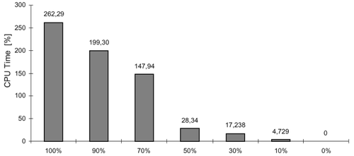
In most cases, safety-critical applications have strict constraints in terms of memory occupation and system performance. The duplication of the whole set of variables and the introduction of a consistency check before every read operation represent the optimum choice from the fault coverage point of view. Duplication of the whole set of variables enables an extremely high percentage of faults to be covered by this software redundancy technique. On the other side, by duplicating a lower percentage of variables one can trade off the obtained fault coverage with the CPU time overhead.

The experimental result shows that duplicating only 50% of the variables is enough to cover 85% of faults with a CPU time overhead of just 28%.
Attention should also be paid to the implementation of the consistency check, as it is usually carried out after each read operation or at the end of each variable's life period. Carefully implementing this check can minimize the CPU time and code size for this application.


- Function parameter duplication
As the detection of errors in data is achieved through duplicating all variables and adding consistency checks after every read operation, special considerations have to be applied according to the procedure interfaces. Parameters passed to procedures, as well as return values, are considered to be variables. Hence, every procedure parameter is duplicated, as well as the return values. A procedure is still called only once, but it returns two results, which must hold the same value. The source listing to the right shows a sample implementation of function parameter duplication.
- Test duplication
To duplicate a test is one of the most robust methods that exists for generic soft error detection. A drawback is that no strict assumption on the cause of the errors (EMI, ESD etc.), nor on the type of errors to expect (errors affecting the control flow, errors affecting data etc.) can be made. Erroneous bit-changes in data-bytes while stored in memory, cache, register, or transmitted on a bus are known. These data-bytes could be operation codes (instructions), memory addresses, or data. Thus, this method is able to detect a wide range of faults, and is not limited to a specific fault model. Using this method, memory increases about four times, and execution time is about 2.5 times as long as the same program without test duplication. Source listing to the right shows a sample implementation of the duplication of test conditions.
- Branching duplication

Compared to test duplication, where one condition is cross-checked, with branching duplication the condition is duplicated.
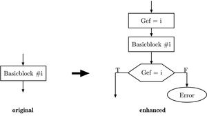
For every conditional test in the program, the condition and the resulting jump should be reevaluated, as shown in the figure. Only if the condition is met again, the jump is executed, else an error has occurred.
- Instruction duplication and diversity in implementation
What is the benefit of when data, tests, and branches are duplicated when the calculated result is incorrect? One solution is to duplicate an instruction entirely, but implement them differently. So two different programs with the same functionality, but with different sets of data and different implementations are executed. Their outputs are compared, and must be equal. This method covers not just bit-flips or processor faults but also programming errors (bugs). If it is intended to especially handle hardware (CPU) faults, the software can be implemented using different parts of the hardware; for example, one implementation uses a hardware multiply and the other implementation multiplies by shifting or adding. This causes a significant overhead (more than a factor of two for the size of the code). On the other hand, the results are outstandingly accurate.
Ports
Reset ports and interrupt ports
Reset ports and interrupts are very important, as they can be triggered by rising/falling edges or high/low potential at the interrupt port. Transient disturbances can lead to unwanted resets or trigger interrupts, and thus cause the entire system to crash. For every triggered interrupt, the instruction pointer is saved on the stack, and the stack pointer is decremented.
Try to reduce the amount of edge triggered interrupts. If interrupts can be triggered only with a level, then this helps to ensure that noise on an interrupt pin will not cause an undesired operation. It must be kept in mind that level-triggered interrupts can lead to repeated interrupts as long as the level stays high. In the implementation, this characteristic must be considered; repeated unwanted interrupts must be disabled in the ISR. If this is not possible, then on immediate entry of an edge-triggered interrupt, a software check on the pin to determine if the level is correct should suffice.
For all unused interrupts, an error-handling routine has to be implemented to keep the system in a defined state after an unintended interrupt.
Unintentional resets disturb the correct program execution, and are not acceptable for extensive applications or safety-critical systems.
Reset differentiation (cold/warm start)
A frequent system requirement is the automatic resumption of work after a disturbance/disruption. It can be useful to record the state of a system at shut down and to save the data in a non-volatile memory. At startup the system can evaluate if the system restarts due to disturbance or failure (warm start), and the system status can be restored or an error can be indicated. In case of a cold start, the saved data in the memory can be considered valid.
External current consumption measurement

This method is a combination of hard- and software implementations. It proposes a simple circuit to detect an electromagnetic interference using the device's own resources. Most microcontrollers, like the ATmega16, integrate analog to digital converters (ADCs), which could be used to detect unusual power supply fluctuations caused by interferences.
When an interference is detected by the software, the microcontroller could enter a safe state while waiting for the aggression to pass. During this safe state, no critical executions are allowed. The graphic presents how interference detection can be performed. This technique can easily be used with any microcontroller that features an AD-converter.
Watchdog
A watchdog timer is an electronic timer that detects abnormal operation of other components and initiates corrective action to restore normal operation. It especially ensures that microcontroller controlled devices do not completely fail if a software error or momentary hardware error occurs. Watchdog timers are typically based on either a monostable timer or digital counter. The timer circuit may be integrated on the microcontroller chip or be implemented as an external circuit. Watchdog timers can significantly improve the reliability of a microcontroller in an electromagnetically-influenced environment.
The software informs the watchdog at regular intervals that it is still working properly. If the watchdog is not informed, it means that the software is not working as specified any more. Then the watchdog resets the system to a defined state. During the reset, the device is not able to process data and does not react to calls.
As the strategy to reset the watchdog timer is very important, two requirements have to be attended:
- The watchdog may only be reset if all routines work properly.
- The reset must be executed as quickly as possible.
Simple activation of the watchdog and regular resets of the timer do not make optimal use of a watchdog. For best results, the refresh cycle of the timer must be set as short as possible and called from the main function, so a reset can be performed before damage is caused or an error occurred. If a microcontroller does not have an internal watchdog, a similar functionality can be implemented by the use of a timer interrupt or an external device.
Brown-out
A brown-out circuit monitors the VCC level during operation by comparing it to a fixed trigger level. When VCC drops below the trigger level, the brown-out reset is immediately activated. When VCC rises again, the MCU is restarted after a certain delay.
See also
- EMC Aware Programming
- Emission Aware Programming
- Electromagnetic compatibility
- List of EMC directives
- Fault-tolerant computer system
- Software fault tolerance
- Fault-tolerant software
Notes
- ↑ Latch-up – also known as Single Event Latch-up (SEL) – is a short circuit of VDD (positive power supply) and VSS (negative power supply). The latch-up is caused by parasitic transistors (transistors that cannot be activated during normal operating conditions) of CMOS circuits. Strong transient disturbances can activate transistors and thermally destroy the device.
- ↑
External links
- ST AN5833:software techniques for improving EMC performance
- The EMC Impact of Embedded Software
- Freescale application note: improving the Transient Immunity Performance of Microcontroller-Based Applications