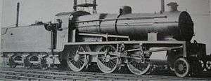
Holcroft valve gear

The Holcroft valve gear was a type of conjugated valve gear designed by Harold Holcroft and used on three-cylinder steam locomotives of the South Eastern and Chatham Railway (SECR). It bore many similarities to the Gresley conjugated valve gear used on the original LNER A1 design. It varied from the Gresley method of operation by using the combination lever assembly instead of the valve spindles to drive the middle cylinder of a three-cylinder design. This had operational advantages over Gresley's design.
Background
When working for the GWR at Swindon, Holcroft schemed out and patented (in 1909) a conjugated valve gear for three-cylinder steam locomotives, which allowed for the elimination of the valve gear for the inside cylinder by deriving the motion for the inside valve from that of the outside valves. This would be done by an assembly of levers behind the cylinder block.
Somewhat later, Nigel Gresley of the GNR had designed and patented his own application of conjugated valve gear (Late 1916) which required further development to enable it to be applied to three cylinders of differing inclination. Gresley was involved with ARLE and he and Holcroft met at the formers office at Kings Cross in January 1919. Holcroft had come up with a practical proposal to allow the Gresley valve gear to operate the inside valve and retain valve events at their correct relationship, by skewing the cylinder and valve axis.
In 1917 Holcroft produced a proposal for a 3-cylinder 4-4-0 for the SECR, which included a conjugation mechanism behind the cylinders to drive the inside valve, but this was not taken up. In February 1919 Holcroft was asked by the SECR CME Maunsell to design a 3-cylinder version of the SECR N class 2-6-0, which became the N1. It proved impractical to locate the mechanism behind the cylinders on this design due to the leading coupled wheel fouling the area required for the gear. This made it necessary to revise the design with side rods to transmit the motion forward to the lever mechanism mounted near the front of the frames. Thus, some of the advantage of 'neatness' and compactness of the original was lost. [1] The gear was also used on the sole K1 and the first of the U1 class.
In the long term, however, the Holcroft gear was not perpetuated on the Southern Railway, and further SR 3-cylinder locomotives were constructed with 3 sets of valve gear.
Design
Three-cylinder locomotives have certain advantages over two-cylinder ones, but a significant disadvantage over a two-cylinder locomotive is the need for a third set of valve gear, normally mounted between the frames where routine maintenance is inconvenient. The conjugation mechanism removes the need for the third set of valve gear, replacing it with a somewhat simpler arrangement of transverse levers.
Conjugated gear is effectively a mechanical adding machine, where the position of the valve for the inside cylinder is the sum of the positions of the two outside cylinders, but reversed in direction. It can also be thought of as a rocking lever between one outside cylinder and the inside cylinder, as is common on 4-cylinder steam locomotives, but with the pivot point being moved back and forth by a lever from the other outside cylinder. See Gresley conjugated valve gear for more detail.
When it proved impractical to mount the conjugation apparatus behind the cylinders on the N1 Holcroft had to revise the design to have the apparatus in front of the cylinders. He did not wish to use an extension of the valve spindles, as on Gresley conjugated valve gear. Instead, Holcroft carried-forward the action of the combination lever assembly that controlled the fore and aft movement of the valve spindle (which admitted "live" steam into the cylinder and ejected "spent" steam out through the ports) to a pivot point connected to a lever from the "inside" valve spindle.[2] The Holcroft variant held an advantage over Gresley’s "conjugated" design, as the valve timing was immune to variations brought about by heat expansion of the valve spindles and flexing of the conjugation assembly when under heavy use.[3] It also had potential maintenance benefits because most of the conjugation mechanism was located outside the locomotive frames and could thus be accessed without an inspection pit.[3]
References
Notes
Bibliography
- Clarke, Jeremy: 'The locomotives of R.E.L. Maunsell, Part 3: The 'Mogul' family – SECR' (Steam World, 2008 (248)), pp. 38–41
- Holcroft, H.: 'Conjugated valve gears for locomotives: their history and development' (Engineer: 181, 1946), Feb 15: pp. 145–147; Feb 22: pp. 168–170; Mar 1: 192–193
- Middlemass, Tom: 'The "Woolworths" — Woolwich Arsenal's tentative entry into main line locomotive building' (Backtrack, 1990 (4)), pp. 148–54