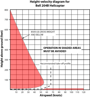
Helicopter height–velocity diagram

The height–velocity diagram or H/V curve is a graph charting the safe/unsafe flight profiles relevant to a specific helicopter. As operation outside the safe area of the chart can be fatal in the event of a power or transmission failure it is sometimes referred to as the dead man's curve. It may also be referred to as the coffin corner, which is an analogous term for fixed-wing aircraft.
In the simplest explanation, the H–V curve is a diagram indicating the combinations of height above ground and airspeed that should be avoided due to safety concerns relating to emergency landings. It is dangerous to operate within the shaded regions of the diagram, because it may be impossible for the pilot to complete an emergency autorotation from a starting point within these regions.[1] The H–V curve will usually contain a take-off profile, where the diagram can be traversed from 0 height and 0 speed to cruise, without entering the shaded areas or with minimum exposure to shaded areas.
The portion in the upper left of this diagram represents a flight profile which will likely prevent the pilot from successfully completing an autorotation primarily because the aircraft does not have sufficient airspeed to enter an efficient autorotation state in time to avoid a crash. This region is sized considering the time delay required for the pilot to realize that there is an emergency and take appropriate action.[1] The shaded area at the lower left is not portrayed in H–V curves for multiengine helicopters capable of safely hovering and flying with a single engine failure. The shaded area on the lower right is dangerous due to the airspeed and proximity to the ground resulting in dramatically reduced reaction time for the pilot in the case of mechanical failure, or other in-flight emergencies.
The following examples further illustrate the relevance of the H–V curve to a single engine helicopter.
At low heights with low airspeed, such as a hover taxi, the pilot can simply cushion the landing with collective, converting rotational inertia to lift. The aircraft is in a safe part of the H–V curve. At the extreme end of the scale (say a three-foot hover taxi at walking pace) even a complete failure to recognise the power loss resulting in an un-cushioned landing would probably be survivable.
As the airspeed increases without an increase in height, there comes a point where the pilot's reaction time would be insufficient to react with a flare in time to prevent a high-speed, and thus probably fatal, ground impact. Even small increases in height give the pilot much greater time to react, thus the bottom right part of the H–V curve is usually a shallow gradient. If above ideal autorotation speed, the pilot's instinct is usually to flare to convert speed to height and increase rotor RPM through coning; which also immediately gets him out of the dead man's curve.[2]
Conversely, an increase in height without a corresponding increase in airspeed will put the aircraft above a survivable un-cushioned impact height, and eventually above a height where rotor inertia can be converted to sufficient lift to enable a survivable landing. This occurs abruptly with airspeeds much below the ideal autorotative speed (typically 40–80 knots). The pilot must have enough time to accelerate to autorotation speed in order to be able to successfully autorotate; this directly relates to a requirement for height. Above a certain height the pilot can achieve autorotation speed even from a 0-knot start, thus putting "high hovers" outside the curve.
The typical safe take-off profile will involve initiation of forward flight from a low hover, only gaining height as airspeed approaches a safe autorotative speed but keeping above the lower right area of the H–V curve.
See also
References
- 1 2 Leishman, J. Gordon (2006). Principles of Helicopter Aerodynamics. New York: Cambridge University Press. pp. 249–250. ISBN 978-0-521-85860-1.
- ↑ Chapter 11: Helicopter Emergencies and Hazards. 6 MB page 11-8. Main page. Rotorcraft Flying Handbook, FAA Manual H-8083-21A. Complete manual, 84 MB, Washington, DC: Flight Standards Service, Federal Aviation Administration, U.S. Dept. of Transportation, 2012.
External links
- http://www.copters.com/pilot/hvcurve.html
- http://www.magnigyro.com/features/HV%20Curve%20for%20Gyroplanes.pdf
- RWS 19 – Height Velocity Diagram with Shawn Coyle Rotary Wing Show, 2015.
