Encoder (digital)

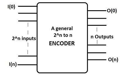
A Simple Encoder or simply an encoder in digital electronics is a one-hot to binary converter. That is, if there are 2n input lines, and at most only one of them will ever be high, the binary code of this 'hot' line is produced on the n-bit output lines.
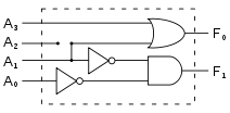
For example, a 4-to-2 simple encoder takes 4 input bits and produces 2 output bits. The illustrated gate level example implements the simple encoder defined by the truth table, but it must be understood that for all the non-explicitly defined input combinations (i.e., inputs containing 0, 2, 3, or 4 high bits) the outputs are treated as don't cares.[1]
One may say it is the reverse of a Decoder in its functioning and that is true in terms of functioning.

| I3 | I2 | I1 | I0 | O1 | O0 | V |
|---|---|---|---|---|---|---|
| 0 | 0 | 0 | 0 | x | x | 0 |
| 0 | 0 | 0 | 1 | 0 | 0 | 1 |
| 0 | 0 | 1 | 0 | 0 | 1 | 1 |
| 0 | 1 | 0 | 0 | 1 | 0 | 1 |
| 1 | 0 | 0 | 0 | 1 | 1 | 1 |
If the input circuit can guarantee at most a single-active input, a simple encoder is a better choice than a priority encoder, since it requires less logic to implement but if not this become the major disadvantage of simple encoder that is they can generate the wrong output when there is more than one input present in a high state (logic state “1”).to rectify this problem a Priority encoder is used.they act on the request of higher priority and the rest cases go in "don't care condition".[2]
Types of Encoder

-to-n Encoders
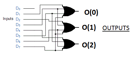
A -to-n encoder has n number of outputs in correspondence to the number of inputs. It thus reduces the number of transmission lines and can be compared to a multiplexer.only one of the inputs become "high" (logic state "1") at a time.
Some typical examples would be 4:2 encoder, 8:3 encoder, 16:4 encoders etc.

| INPUT | OUTPUT | |||||||||
|---|---|---|---|---|---|---|---|---|---|---|
| D7 | D6 | D5 | D4 | D3 | D2 | D1 | D0 | O(0) | O(1) | O(2) |
| 0 | 0 | 0 | 0 | 0 | 0 | 0 | 0 | X | X | X |
| 0 | 0 | 0 | 0 | 0 | 0 | 0 | 1 | 0 | 0 | 0 |
| 0 | 0 | 0 | 0 | 0 | 0 | 1 | 0 | 0 | 0 | 1 |
| 0 | 0 | 0 | 0 | 0 | 1 | 0 | 0 | 0 | 1 | 0 |
| 0 | 0 | 0 | 0 | 1 | 0 | 0 | 0 | 0 | 1 | 1 |
| 0 | 0 | 0 | 1 | 0 | 0 | 0 | 0 | 1 | 0 | 0 |
| 0 | 0 | 1 | 0 | 0 | 0 | 0 | 0 | 1 | 0 | 1 |
| 0 | 1 | 0 | 0 | 0 | 0 | 0 | 0 | 1 | 1 | 0 |
| 1 | 0 | 0 | 0 | 0 | 0 | 0 | 0 | 1 | 1 | 1 |
See also
- Decoders.
- Multiplexer.(MUX)
- Priority Encoder.
- Encoder.
References
- ↑ "Binary Encoders And Their Applications". Electronics Hub. 2015-06-29. Retrieved 2017-05-01.
- ↑ "View source for Priority encoder". Wikipedia.