Audio and video interfaces and connectors
Audio connectors and video connectors are electrical connectors (or optical connectors) - plugs and sockets - for carrying audio signal and video signal.
Audio interfaces and video interfaces define physical parameters and interpretation of signals. For digital audio and digital video, this can be thought of as defining the physical layer, data link layer, and most or all of the application layer. For analog audio and analog video these functions are all represented in a single signal specification like NTSC or the direct speaker-driving signal of analog audio. Physical characteristics of the electrical or optical equipment includes the types and numbers of wires required, voltages, frequencies, optical intensity, and the physical design of the connectors. Any data link layer details define how application data is encapsulated (for example for synchronization or error-correction). Application layer details define the actual audio or video format being transmitted, often incorporating a codecs not specific to the interface, such as PCM, MPEG-2, or the DTS Coherent Acoustics codec. In some cases, the application layer is left open; for example, HDMI contains an Ethernet channel for general data transmission.
Some types of connectors are used by multiple hardware interfaces; for example, RCA connectors are defined both by the composite video and component video interfaces, but DVI is the only interface that uses the DVI connector. This means that in some cases not all components with physically compatible connectors will actually work together.
Some of these connectors, and other types of connectors, are also used at radio frequency (RF) to connect a radio or television receiver to an antenna or to a cable system; RF connector applications are not further described here. Analog A/V connectors often use shielded cables to inhibit radio frequency interference (RFI) and noise.
For efficiency and simplicity, the same codec or signal convention is used by the storage medium. For example, VHS tapes can store a magnetic representation of an NTSC signal, and the specification for Blu-ray Discs incorporates PCM, MPEG-2, and DTS. Some playback devices can re-encode audio or video so that the format used for storage does not have to be the same as the format transmitted over the A/V interface (which is helpful if a projector or monitor cannot handle a newer codec).
Interfaces and their connectors
| Interface | Connectors | ||
|---|---|---|---|
| Audio or video | Digital or analog | Description | |
| Audio only | Analog | Often unmarked on consumer audio equipment since it is so common, or labelled with headphones symbol or as "line out". Computers and other equipment sometimes use Microsoft-Intel color coding scheme, especially when there are multiple input/output plugs. | 3.5 mm TRS minijack |
| Balanced audio | 6.35 mm TRS audio jack (shielded twisted pair), XLR (shielded twisted pair) | ||
| Digital | S/PDIF (Sony/Philips Digital Interconnect Format). Via coaxial or optical cables. | RCA Jack (coaxial), TOSLINK (optical), BNC (rare) | |
| AES3 (also known as AES/EBU) | RCA Jack (coaxial), XLR (shielded twisted pair), TOSLINK (optical), BNC | ||
| Video only | Analog | Video Graphics Array (VGA) | D-subminiature 15-pin |
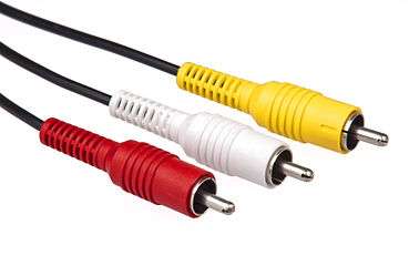
| Composite. Often designated by the CVBS acronym, meaning "Color, Video, Blank and Sync". | RCA jack, normally yellow (often accompanied with red and white for right and left audio channels respectively) | ||
| S-Video (Separate Video). Carries standard definition video and does not carry audio on the same cable. | Mini-DIN 4-pin | ||
| Component. In popular use, it refers to a type of analog video information that is transmitted or stored as three separate signals. Either RGB interfaces or YPbPr | 3 RCA Jacks | ||
| Composite, S-Video, and Component | VIVO = Mini-DIN 9-pin with breakout cable. | ||
| Digital and analog | Digital Visual Interface (DVI) | DVI connector | |
| Video and audio | Analog | SCART (Peritel) | SCART |
| Digital | High-Definition Multimedia Interface (HDMI),BNC | HDMI connector | |
| DisplayPort | DisplayPort connector | ||
| HDBaseT | 8P8C connector | ||
| IEEE 1394 "FireWire" | FireWire or i.LINK connectors | ||
Multiple signals
Some connectors can carry both audio and video signals simultaneously:
- HDMI combines DVI-compliant uncompressed video data with compressed or uncompressed audio, and supports other protocols.
- FireWire is used on Camcorders, commonly ones using MiniDV tapes, and high-end audio equipment.
- Digital Media Port a connector proposed by Sony on its audio/video products
- DisplayPort carries digital audio and video, as well as auxiliary information
- Mini DisplayPort smaller form factor of display port that performs the same function
- Thunderbolt
- Unified Display Interface (UDI)
- Mobile High-Definition Link (MHL)
- F connectors are used with RF modulators for televisions without direct inputs
- SCART, now the most common in Europe
- TRS phone connectors with more than one ring, or Sony's hybrid RCA with a TRS pin
- Coaxial cable/RG-6/RG-59/Cable television (CATV)
Other composite connectors that carry video, audio, power, and USB:
- ADC, now-defunct Apple Display Connector
- Apple 30-pin dock connector, a docking cradle for Apple iPod, iPhone and iPad
- Portable Digital Media Interface (PDMI) - includes DisplayPort for digital video and audio, analog audio, USB 3.0, and power
- USB-C - can include USB 3.1, DisplayPort, Thunderbolt, superMHL, HDMI, and power; as well as analog audio with an adapter
S/PDIF
The electrical coaxial cable (with RCA jacks) or optical fibre (TOSLINK).
Note that there are no differences in the signals transmitted over optical or coaxial S/PDIF connectors—both carry exactly the same information. Selection of one over the other rests mainly on the availability of appropriate connectors on the chosen equipment and the preference and convenience of the user. Connections longer than 6 meters or so, or those requiring tight bends, should use coaxial cable, since the high light signal attenuation of TOSLINK cables limits its effective range.
HDMI

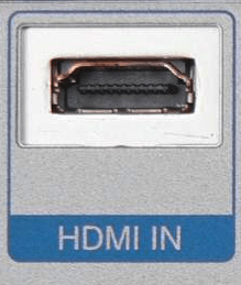
High-Definition Multimedia Interface (HDMI) is a compact audio/video standard for transmitting uncompressed digital data.
There are three HDMI connector types. Type A and Type B were defined by the HDMI 1.0 specification. Type C was defined by the HDMI 1.3 specification.
Type A is electrically compatible with single link DVI-D. Type B is electrically compatible with dual link DVI-D but has not yet been used in any products.
IEEE 1394 "FireWire"

IEEE 1394 FireWire is a digital data transfer protocol commonly used for digital cameras (common on MiniDV tape camcorders), but also used for computer data and audio data transfers. In the United States, cable TV converter set top boxes by law[1] also have the connection for transferring content directly to a TV (if equipped with a port) or computer for viewing. 1394 can also use coaxial cable as a medium for longer runs.
Unlike Point-to-Point connections listed above, IEEE 1394 is able to host several signals on the same wire, with the data delivered and shown on the destination set. It is also fully bi-directional, with its full bandwidth used in one direction or the other, or split directions up to its maximum.[2]
DisplayPort

DisplayPort is a digital display interface standard (approved May 2006, current version 1.4 published on March 1 2016). It defines a new license-free, royalty-free, digital audio/video interconnect, intended to be used primarily between a computer and its display monitor, or a computer and a home-theater system.
The video signal is not compatible with DVI or HDMI, but a DisplayPort connector can pass these signals through. DisplayPort is a competitor to the HDMI connector, the de facto digital connection for high-definition consumer electronics devices.
Audio connectors
Audio connectors are used for audio frequencies. They can be analog or digital.
Single-wire connectors used frequently for analog audio include:
- Banana connectors
- Spade connectors
- Five-way binding posts and banana plugs for loudspeakers
- Fahnestock clips on early breadboard radio receivers.
- Euroblock "European-style terminal block" or "Phoenix connectors", screw terminal connectors used for audio and control signals
- Multi-conductor connectors:
- DB25 is for multi-track recording and other multi-channel audio, analog or digital
- DIN connectors and mini-DIN connectors
- Euroblock "European-style terminal block" or "Phoenix connectors", screw terminal connectors used for audio and control signals
- RCA connectors, also known as phono connectors or phono plugs, used for analog or digital audio or analog video
- Speakon connectors by Neutrik for loudspeakers
- Phone connector also known as tip-ring-sleeve (TRS) or tip-sleeve plug, phone plug, jack plug, mini-jack, and mini-stereo. This includes the original 6.35mm (quarter inch) jack and the more recent and standard 3.5mm (miniature or 1/8 inch) and 2.5mm (subminiature) jacks, both mono and stereo (balanced) versions.[3]
- XLR connectors, also known as Cannon plugs, used for analog or digital balanced audio with a balanced line.
- Digital audio interfaces and interconnects:
- ADAT interface (DB25)
- AES/EBU interface, normally with XLR connector
- S/PDIF, either over electrical coaxial cable (with RCA jacks) or optical fiber (TOSLINK).
Phone connector

A phone connector (tip, ring, sleeve) also called an audio jack, phone plug, jack plug, stereo plug, mini-jack, or mini-stereo. This includes the original 6.35mm (quarter inch) jack and the more recent 3.5mm (miniature or 1/8 inch) and 2.5mm (subminiature) jacks, both mono and stereo versions.
DIN

A DIN connector is a connector that was originally standaidzrdized by the Deutsches Institut für Normung (DIN). Mini-DIN is a variation.
BNC

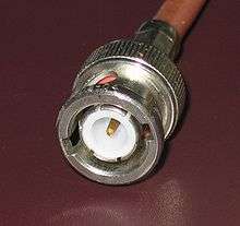
The BNC (Bayonet Neill Concelman) connector is a very common type of RF connector used for terminating coaxial cable.
TOSLINK

TOSLINK or Optical Cable is a standardized optical fiber connection system.
XLR

XLR connector plugs and sockets are used mostly in professional audio and video electronics cabling applications. XLR connector are also known as Cannon plugs after their original manufacturer. They are used for analog or digital balanced audio with a balanced line
Digital audio interfaces and interconnects with the AES/EBU interface also normally use an XLR connector.
RCA

RCA connectors, also known as phono connectors or phono plugs, are used for analog or digital audio or analog video. These were first used inside pre-World-War-II radio-phonographs to connect the turntable pickup to the radio chassis. They were not intended to be disconnected and reconnected frequently, and their retaining friction was quite sufficient for their original purpose. Furthermore, the design of both cable and chassis connectors was for minimum cost. Initially intended for audio frequency connections only, the RCA plug was also used for analog composite video and non-critical radio-frequency applications.
Video connectors
Video connectors carry only video signals. Common video-only connectors include:
- Component video aka YPbPr (3 RCA or BNC; or D-Terminal)
- Composite video (1 RCA, Antenna socket, or BNC)
- DB13W3 ("13W3" computer video connector)
- DMS-59, single connector carrying two DVI and two VGA
- Musa, British connector used in broadcasting and telecommunications
- PAL connector, common in Europe as an antenna connector
- S-Video (1 Mini-DIN)
- SDI - Broadcast grade digital interface over BNC cables
- VGA connector A type of D-sub connector standard on most video cards
- Mini-VGA Found on some laptop computers
- 5 BNC Connectors can also be used to carry the VGA signal as R, G, B, HSync, VSync
- Digital Visual Interface (DVI) A hybrid analog/digital connector commonly found on PC graphics cards and LCD monitors
- Mini-DVI Found on some Apple laptops
- Enhanced Graphics Adapter (EGA)
- RGB interface
- RGBI interface
- VESA Digital Flat Panel
Mini-DIN

The Mini-DIN connectors are a family of multi-pin electrical connectors used in a variety of applications. Mini-DIN is similar to the larger, older DIN connector. Both are standards of the Deutsches Institut für Normung, the German standards body.
D-subminiature

D-subminiature or D-sub is a common type of electrical connector used particularly in computers. Calling them "sub-miniature" was appropriate when they were first introduced, but today they are among the largest common connectors used in computers. The DB25 is used for multi-track recording and other multi-channel audio, analog or digital (ADAT interface (DB25)), and was the standard connector for IBM compatible PC printer connection before USB and other connections became popular. It offered 8 simultaneous data pathways to the printer.
Video In Video Out

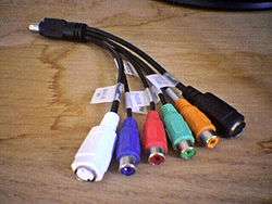
Video In Video Out, usually seen as the acronym VIVO (commonly pronounced vee-voh), is a graphics card port which enables some video cards to have bidirectional (input and output) video transfer through a Mini-DIN, usually of the 9-pin variety, and a specialised splitter cable (which can sometimes also transfer sound).
VIVO is found predominantly on high-end ATI video cards, although a few high-end NVIDIA video cards also have this port. VIVO on these graphics cards typically supports Composite, S-Video, and Component as outputs, and composite and S-Video as inputs. Many other video cards only support component and/or S-Video outputs to complement Video Graphics Array or DVI, typically using a component breakout cable and an S-Video cable.
DVI Connector
 Male DVI connector pins (view of plug)  Male M1-DA connector pins (view of plug) |
The Digital Visual Interface (DVI) is a video interface standard designed to maximize the visual quality of digital display devices such as flat panel LCD computer displays and digital projectors. It is designed for carrying uncompressed digital video data to a display. There are four basic connectors:
The connector also includes provision for a second data link for high resolution displays, though many devices do not implement this. In those that do, the connector is sometimes referred to as DVI-DL (dual link). So we need to know two things about the connector:
|
Color codes
Audio
white RCA/TS analogue audio, left channel;
also mono (RCA/TS), stereo (TRS only),
or undefined/otherblack RCA/TS/TRS grey RCA/TS/TRS red RCA/TS analogue audio, right channel orange RCA S/PDIF digital audio
For computers:
green TRS 3.5 mm stereo output, front channels black TRS 3.5 mm stereo output, rear channels grey TRS 3.5 mm stereo output, side channels gold TRS 3.5 mm dual output, center and subwoofer blue TRS 3.5 mm stereo input, line level pink TRS† 3.5 mm mono microphone input - † Although the mic input is usually mono, the input is still a TRS phone socket. Many mono 'computer' mics are fitted with TRS plugs. The tip is for the MIC and the ring is for power (to power an electret-condenser style MIC).
There are exceptions to the above:
- Hosa cables use grey and orange for left and right analogue channels.
- RadioShack cables sometimes use grey and black for left and right.
- Older sound cards had non-standard colour codes until after PC 99, prior to that there were no colors at all.
PC System Design Guide audio
Older sound cards had no common standard color codes until after PC 99. The PC System Design Guide (also known as the PC 97, PC 98, PC 99, or PC 2001 specification) is a series of hardware design requirements and recommendations for IBM PC compatible personal computers, compiled by Microsoft and Intel Corporation during 1997–2001. PC 99 introduced a color code for the various standard types of plugs and connectors used on PCs.
The color codes for audio plugs follow:[4]
Orange TRS 3.5 mm Output, subwoofer Blue TRS 3.5 mm Input, line level Pink TRS† 3.5 mm microphone input Lime TRS 3.5 mm Output, front channels Brown TRS 3.5 mm Output, 'Right-to-left speaker' Gold TRS 3.5 mm MIDI/game - † Though the input is often mono, the actual connector is usually still a 3-conductor TRS phone minijack. Many mono computer microphones have 3-conductor TRS plugs.
Video
yellow RCA/BNC composite video red RCA/BNC red or Pr/Cr chrominance green RCA/BNC green or luminance blue RCA/BNC blue or Pb/Cb chrominance white BNC horizontal sync black BNC vertical sync
Newer connectors are identified by their shape and not their colour.
See also
- Speaker wire
- Category:Telecommunications standards
- Computer port (hardware)
- Speakon connectors
- Y-cable
References
- ↑ "Archived copy". Archived from the original on 2010-07-31. Retrieved 2010-06-04. All Cable TV box have working 1394 ports, FCC rule CS Docket 97-80" and "section 47 C.F.R. 76.640(b)(4)
- ↑ "Archived copy" (PDF). Archived from the original (PDF) on 2011-06-06. Retrieved 2010-06-04. Demonstrating the multi-device capabilities of IEEE A/V network.
- ↑ 2.5mm Audio Cables Archived September 26, 2013, at the Wayback Machine.
- ↑ PC 99 System Design Guide, Intel Corporation and Microsoft Corporation, 14 July 1999. Chapter 3: PC 99 basic requirements (PC 99 System Design Guide (Self extracting .exe). Requirement 3.18.3: Systems use a color-coding scheme for connectors and ports. Accessed 2009-02-05
