Algorithmic state machine
The algorithmic state machine (ASM) method is a method for designing finite state machines. It is used to represent diagrams of digital integrated circuits. The ASM diagram is like a state diagram but less formal and thus easier to understand. An ASM chart is a method of describing the sequential operations of a digital system.
ASM method
The ASM method is composed of the following steps:
- 1. Create an algorithm, using pseudocode, to describe the desired operation of the device.
- 2. Convert the pseudocode into an ASM chart.
- 3. Design the datapath based on the ASM chart.
- 4. Create a detailed ASM chart based on the datapath.
- 5. Design the control logic based on the detailed ASM chart.
ASM chart
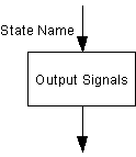
An ASM chart consists of an interconnection of four types of basic elements: state names, states, condition checks and conditional outputs. An ASM state, represented as a rectangle, corresponds to one state of a regular state diagram or finite state machine. The Moore type outputs are listed inside the box.

State name: The name of the state is indicated inside the circle and the circle is placed in the top left corner or the name is placed without the circle.

State box : The output of the state is indicated inside the rectangle box

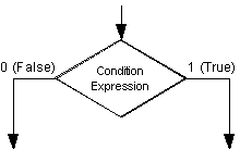
Decision box: A diamond indicates that the stated condition expression is to be tested and the exit path is to be chosen accordingly. The condition expression contains one or more inputs to the FSM (Finite State Machine). An ASM condition check, indicated by a diamond with one input and two outputs (for true and false), is used to conditionally transfer between two states or between a state and a conditional output. The decision box contains the stated condition expression to be tested, the expression contains one or more inputs of the FSM.

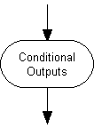
Conditional output box: An oval denotes the output signals that are of Mealy type. These outputs depend not only on the state but also the inputs to the FSM.
Datapath
Once the desired operation of a circuit has been described using RTL operations, the datapath components may be derived. Every unique variable that is assigned a value in the RTL program can be implemented as a register. Depending on the functional operation performed when assigning a value to a variable, the register for that variable may be implemented as a straightforward register, a shift register, a counter, or a register preceded by a combinational logic block. The combinational logic block associated with a register may implement an adder, subtracter, multiplexer, or some other type of combinational logic function.
Detailed ASM chart
Once the datapath is designed, the ASM chart is converted to a detailed ASM chart. The RTL notation is replaced by signals defined in the datapath.
See also
References
- Christopher R. Clare: Designing Logic Systems Using State Machines, McGraw-Hill 1973, ISBN 0-07-011120-0.
- Sunggu Lee: Computer Design: An Example of Advanced Digital Logic Design, Prentice-Hall 2000, ISBN 0-13-040267-2.
- Sunggu Lee: Advanced Digital Logic Design: Using VHDL, State Machines, and Synthesis for FPGAs, Thomson 2006, ISBN 0-534-46602-8.
- Stephen D. Brown, Zvonko Vranesic: Fundamentals of Digital Logic with VHDL Design.
External links
- Brief Introduction to ASM Charts
- ASM++: a modern Algorithmic State Machine methodology for RTL designs