Sensors for Arc Welding
The general term “Sensors for Arc Welding” denotes devices which – as a part of a fully mechanised welding equipment – are capable to acquire information about position and, if possible, about the geometriy of the intended weld at the workpiece and to provide respective data in a suitable form for the control of the weld torch position and, if possible, for the weld process parameters.
Introduction
The quality of a weld depends, besides the weld parameters which are important for the welding process (e.g. voltage, current, wire feed and weld speed) also mainly from the type of input of process energy and of the used filler material. The positioning of the torch exerts a direct influence on the material flow. The heat input for the melting of the component edges and the steady heat flow are, furthermore, directly connected with the torch guidance and exert substantical influence on the weld quality and on the resulting residual stresses. In fully mechanised and automated shielded gas welding, the inaccuracies of torch guidance, workpiece handling, groove preparation and thermal distortion are adding to the variations of the edge position and edge geometry. In fully mechanised welding, the information which is required for the weld quality is detected via sensors. Sensors are applied for checking the position of the component (detection of weld start and end of weld), for joint tracking and for the adaptation of the process parameters to changes of the joints/grooves. It is possible to use the sensors online (together/at the same time with the welding process) or offline (in a separate working step before welding). Sensors are mainly used in online joint tracking.
Principles

All physical principles which are capable to provide information about the position of an object are suitable to serve as the starting basis for a sensor function. The ambient conditions prevailing during arc welding and also the requirements which are made by fully mechanised equipments have, however, many restrictions as a consequence. Figure 1 depicts the system overview. The monitoring strategy of the sensor (process or geometry) has been chosen as the superordinate criterion, the further subdivision is orientated on the measuring principle. A further distinctive feature of sensor systems is their design. Leading sensors are, thus, marked by the fact that measuring point and joining point are not located in the same position. Here, the measuring and joining process are mainly running in sequence. For making position-relevant statements about the welding process, those systems require calibration of the relative position. If process-oriented sensors are used, the measuring point and the joining point are identical. What the measuring principles all have in common is the fact that through the evaluation of the sensor signal, geometrical information about the joint and its relative position to the measuring head is provided. The individual active principles allow different processing speed for acquiring the information.
Geometry-oriented
Geometry-oriented sensors acquire their signals from the geometry of the groove or from an edge or area the course of which is in accordance with the groove.
Tactile sensors
Electric contact sensors for joint tracking and/or work piece measurement are representing one type of tactile sensors. The sensor makes electric contact with the workpiece, the electrically conductive workpiece is included into the measuring circuit of the sensor. The mechanical contact sensors belong to the second category of the tactile sensors. The mechanical deflection of a scanning element which makes contact with the workpiece is evaluated.
Electric contact sensors
Following a determined searching strategy, the electric contact sensor systems are scanning the weld start or other track points via contacting the work piece with parts/components which have been subjected to voltage (direct voltage of several ten Volt up to 1 KV, depending on material and surface) of the welding equipment (shielding gas nozzle, welding electrode, stylus, or similar.) This means the offline-measuring of the weld start, the part position or part geometry before welding. Knowing the scheduled path, a transformation of the track points in accordance with the measured conditions is carried out. In this case, corrective action is not carried out during the welding process.
Thermal
Here, the heat flow is measured with two thermo-couples which are arranged on the welding torch, the thermal flow is used for the side/lateral- and height control of the torch. The orientation of the torch towards the groove is detected via the comparison of the sensor temperature of the two thermo-couples. If the orientation of the torch is symmetrical, the difference of the radiated thermal flow equals to zero, so do the temperature differences of the thermo-couples. Dependent on the lateral misalignment of the torch the thermo-couples are subject to different heat flows, by the deformation of the arc and also by the changed position of the molten pool.
Mechanical contact


Mechanical contact systems transform the deflection of the scanning element directly into electric control signals. The following transformer principles are differentiated:
- micro-switch
- potentiometer
- optical transformer (light barriers or similar)
- inductive transformer
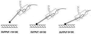
Due to the required distance of the acting/break points in one level, transformers which are equipped with micro-switches have a control hysteresis in the working point which has the consequence of a restricted reproducible accuracy. Electric displacement of the working point is not possible. The other, above-mentioned transformer systems (the use of optical systems is probably limited due to design reasons) produce analogous signals in proportion to the scanning element deflection and allow thus the error-proportional weld head tracking and also the electric working point displacement through the superordinate control, e.g. in multiple layer welding. The output signals of the most commonly used inductive measuring transformer systems are between 0 and 10 V DC, depending on the scanning element deflection (Figure 2).
Boundary conditions
Any impairment of the electric contact between sensor scanning element and workpiece is, in the case of electric-contact sensors, problematic, e.g. welding spatters at the shielding gas nozzle, scale and rolling skin on the workpiece surface or through a wire electrode end which has molten spheroidally and has adherence of slag. When mechanical-contact sensors are used, the scanning elements must be adapted to the respective groove shapes. Butt welds with a square butt joint preparation must have a groove gap of more than 3 mm; in overlap joints the top plate must have a thickness of more than 3 mm. The sensor must be mounted separately from the welding torch. Thus, the groove scanning is mainly carried out in a leading position in front of the torch. If the welds are mainly straight, this adjustment is no problem. It is also possible to use scanning element arrays (e.g. fork callipers or separated scanning elements for height and lateral scanning which allow scanning in the torch level and thus weld scanning which is almost free from errors. Apart from the torch guidance along a weld groove, mechanical contact sensors can also be applied for detection of the weld start and end of the weld.
Optical
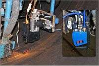
Optical sensors belong to the group of non-contact measuring, geometry-oriented sensors (Figure 1). For information retrieval, the weld groove is scanned via a radiation detector which records the emitted optical radiation of the measured object. Semiconductor image sensors are applied for the detection of radiation. The optical measuring principles are differentiated into sensors with and without active structured lighting. If there is no active structured lighting, a camera is used for signal acquisition. The camera observes the workpiece and extracts the required information from the two-dimensional halftone picture. Active structured lighting means the application of a light source for the defined lighting of specified regions of the part. For the subsequent acquisition, single photo elements, lines or arrays can be used, depending on their design.
Operating mode

For optical measurement without active structured lighting, a camera is directed on the region of the weld groove and the scene of interest is observed directly. This is used, for example, for SA welding processes in order to provide the welder with a live photograph of the weld groove on the monitor. We know two semiconductor technologies for image sensing. The CCD camera (CCD: Charged Coupled Device) is the best known, most widely spread camera type, it is also used in standard video cameras. If a CMOS image sensor has been used, the high input dynamics allow, even with a burning arc, to record a usable image of the weld groove. The method of optical measuring technique with active structured lighting, mainly generated by a laser with a defined wavelength, is often used for the automation of welding processes. It is differentiated between 1, 2 and 3-D measuring systems. Since measuring in the arc directly is not possible, a defined distance (advance) which depends on the type and size of the arc itself must be maintained.
If one-dimensional measuring systems are used, the distance from sensor to workpiece surface is determined. This is carried out via measurement of the running time. A further, frequently used method is laser triangulation (Figure 4).
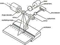
The distance of the workpiece is determined from the known dimensions of the sensor and the triangulation angle α. This type of one-dimensional optical distance measurement systems is widely used in the field of industrial automation technique and is therefore offered by many companies. In automated welding, they are often used for the detection of the part and/or groove position before the start of the welding process. There are different types of design of the two-dimensionally measuring sensor systems. From the 1D triangulation sensor, the two-dimensional laser scanner can be derived from the oscillation movement. Here, the groove geometry is detected via a scanning movement transverse to the groove (Figure 5). This is mainly carried out via a movable mirror unit which is integrated in the sensor head.


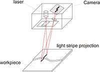
As an alternative, an oscillating movement of the entire sensor head can be carried out, this is, however, only considered a special application of a one-dimensionally measuring system. An advantage of the laser scanner is that, with according processing speed, the lighting conditions can be adapted for every single point-shaped distance measurement which results in illumination uniformity. Moreover, due to the point-shaped illumination, the laser point is through the concentrated laser power and also through appropriate optical filters, compared with the interfering arc radiation, easier to detect by the detection element. The light-section sensor avoids the disadvantage of moving parts in the sensor head (Figure 6). Here, the surface is not scanned pointwise, the entire geometry is, moreover, captured in one image. For this purpose, the point-shaped laser beam is expanded via an optics to a line which is projected onto the surface of the workpiece transverse to the groove in accordance with the scan line of the scanner. The laser line is, in accordance with the same geometrical principle of triangulation, again acquired with a detector element, this time, however, two-dimensionally. For the acquisition, CCD and CMOS cameras with the above-mentioned properties can be used.


As the output signal after the pre-processing of sensor signals with a laser scanner and light-section sensor, the so-called height profile of the measured groove geometry is achieved. It represents the surface of the workpiece along the section at the projected laser line. 3 D measuring systems with active illumination are mainly using the light-section method in combination with the projection of several parallel laser lines. In doing so, each line generates a height profile. Through the arrangement of several lines along the weld groove, a further dimension is achieved which shows the change of the height profiles of the groove geometry. Through the number of the lines, the resolution in groove longitudinal direction is increasing, however, the data processing expenditure is also increasing. Similar to the projection of several parallel lines, the measurement via a projected circle or other geometrical figures on the workpiece surface is possible.
Boundary conditions
What all optical measuring methods have in common is that the determined groove points must be transformed from the sensor coordinates of the cameras into machine and/or work piece coordinates. To this end, they must be calibrated on test work pieces before the welding process takes place and calibration matrices must be provided. Moreover, for the application of image processing algorithms, information about the groove profile must also be provided in advance. This is carried out via teaching of templates, input of geometrical parameters or teach-in via test work pieces. A more comprehensive image processing for 2 and 3 D sensor systems requires normally a PC system for the evaluation; this is why commercially available PC interfaces are used for data exchange, uniform sensor interfaces do, however, not yet exist.
Application problems
In optical sensor systems, problems occur due to the operation principle through the scattered light of the open arc. Therefore, measuring in the working point directly is in most cases not possible when optical sensors are used, a certain advance/distance must be maintained. Further process trouble stems from weld spatters which may exert a negative influence on the detection results. Screening systems between sensor and torch provide a remedy to a certain extent. The direct observation of the arc with special cameras for process monitoring remain an exception. The running of the sensor in front of the arc causes the limited accessibility of corners in the parts. In order to reduce this problem, a design/structure which is as compact as possible and a short advance distance are most important. The pre-defined orientation of the sensor is, moreover, restricting the working space of the robot. For untroubled operation of the optical components also stronger soiling/impurification (dust and deposition of weld fume particles) should be avoided, if possible. Exchangeable protective glasses and safety screens in the form of compressed air curtains provide a remedy. The quality of the surface which is to be measured has substantial influence on the measuring result. If the surface is strongly reflecting, unwanted reflection and faulty measurements may occur, lustreless surfaces are less difficult. Ever-changing surface qualities also lead to problems. Since optical systems are equipped with semiconductor detectors and comprehensive electronics, it is most important to pay attention to safe electro-magnetic screening. This applies to the sensor, the image processing unit and the connecting cables thereof. Sensor systems with active laser illumination are reacting particularly sensitive to strong temperature fluctuations since the emitted light wavelength of the used laser diodes depends on the temperature of the laser. If the ambient temperature and thus the wavelength of the active illumination are changing, the light is no longer capable to penetrate through the narrow-band optical filter to the photodetector. Therefore, appropriate screening against the welding process or the cooling of the sensor head is required. Depending on the applied laser power, particular caution must be taken when sensors with active illumination are applied. The wavelength of the applied systems are often in the field of vision, which means the classification into the hazard classes 3A and 3B. The respective accident prevention regulations must be strictly adhered to. The application of optical sensors demands the consideration of following points:
- consideration of the restriction of the accessibility and of the working space
- screening against interfering light coming from the open arc and weld spatters
- attention must be paid to the reflection properties of the measured surface
- soiling of the optical components must be avoided
- electromagnetic screening of the electronic components required
- temperature fluctuations of the sensor must be compensated
- caution when working with laser radiation
Inductive
Inductive sensors evaluate the attenuation of a high-frequency electro-magnetic field which has been generated by eddy currents in the work piece. The application of single-coil design types allows side or height correction. Multiple-coil sensors allow correction in two coordinate directions and, moreover, influence on the weld torch orientation.
Capacitive
Capacitive sensors measure the capacity between the work piece and an electrically conductive plate with small dimensions. They offer the possibility of distance measurement in media with unchanged dielectricity constant.
Process-oriented
Process-oriented sensors are acquiring their signals from the primary or secondary process parameters. Arc sensors are using the primary process parameters (weld current and/or voltage) of one moving or two unoscillated arcs for the generation of height and side/lateral correction signals. These sensors require, of course, also a scannable groove geometry; the measuring and the joining point are, however, compared with geometry-oriented sensors, located in the same position.
Arc

Stable working points in arc welding are developing as interface between process characteristic and power source characteristic (Figure 7). The process characteristic specifies the connection between a stable arc voltage and the appropriate current rating of the process under constant boundary conditions. A family of characteristics is achieved via the variation of the arc length / torch distance.
In TIG welding
TIG welding belongs to the welding processes with non-melting electrode. Therefore, the process characteristic is often designated as arc characteristic. A direct change of the working distance is compensated via the length of the arc. As a result, the arc resistance is changing. Short arcs have a lower electric resistance than long arcs. In TIG welding, typically power sources with a steeply drooping characteristic are applied. A change of the arc length leads, therefore, directly to the change of the process voltage. A comparative measurement allows the determination of the distance to the workpiece.
In GMA Welding

In GMA welding, the process characteristic in the voltage-current diagram is a result from the interaction of the electric properties of the wire stick-out and of the arc. In principle, stable working points are achieved through the application of suitable power source characteristics or through super-imposed control strategies.
There is a stable equilibrium in point 1 of Figure 8 where the energy which has been input into the process is sufficient for the melting of the continuously fed wire electrode. In the case of a rapid change of distance, the arc compensates the length change, point 2. The lower resistance of the short arc brings about the increase of the current intensity which leads to the faster melting of the wire stick-out until again a stable working point is reached, point 3. This compensation process takes approximately between 100 and 200 ms. The arc sensor evaluates the remaining change in current intensity between point 1 and point 3 in order to achieve a distance-proportionate parameter. In principle, this evaluation concept is also applicable to pulsed arc welding. The concept which has been specified above is, in the case of most arc sensors, extended by the transversal scanning of the groove geometry. The deflection of the process to the fusion faces allows the comparative measurement of the torch distance. By calculating the difference of the distance values, the lateral positioning of the torch can be evaluated. The mean value of both distance values indicates the height of the torch above the groove. Different concepts are applied for the deflection (Figure 9). Mechanical oscillation is most widely spread and is frequently used, especially with robots. Basically, fast deflectory systems, e.g. with magnetic or rotatory deflection offer the improvement of the signal rate and the signal quality, a higher apparatus expenditure must, however, be calculated when these systems are used. In double-wire technique, both fusion faces are scanned at the same time with one wire each.
Boundary conditions
Arc sensors are evaluating the stable working points in arc welding. Disturbance variables of the process must be compensated via suitable filtering and evaluation strategies which are not susceptible to disturbances. In the case of a simultaneous height and side control attention must be paid to the fact that only those groove geometries are suitable for arc sensor systems whose geometry allows the lateral position determination via comparative measurement of the fusion faces. V-type welds and fillet welds are suitable without any restrictions. Square butt welds without gap are not suitable for side/lateral control. Commercially available arc sensors are, so far, not applicable for aluminium materials.
Secondary process parameters
Sensor types which are observing the molten pool are restricted in their applicability range by the fact that molten pool size and arc radiation are dependent on geometrical factors, e.g. material density or composition (alloying constituents). The optical observation of the molten pool region determines changes of the molten pool contour. The deflection from a contour which is defined as “ideal” is interpreted as malposition or as a change of the process behaviour and is compensated subsequently.
Spectral analysis

The spectral analysis of the process signals compares the emission spectres of the arc or of the molten pool with assumend ideal values. Deflections point to a changed chemical composition or to energetic changes of the process zone.