Quantization (image processing)
Quantization, involved in image processing, is a lossy compression technique achieved by compressing a range of values to a single quantum value. When the number of discrete symbols in a given stream is reduced, the stream becomes more compressible. For example, reducing the number of colors required to represent a digital image makes it possible to reduce its file size. Specific applications include DCT data quantization in JPEG and DWT data quantization in JPEG 2000.
Color quantization
Color quantization reduces the number of colors used in an image; this is important for displaying images on devices that support a limited number of colors and for efficiently compressing certain kinds of images. Most bitmap editors and many operating systems have built-in support for color quantization. Popular modern color quantization algorithms include the nearest color algorithm (for fixed palettes), the median cut algorithm, and an algorithm based on octrees.
It is common to combine color quantization with dithering to create an impression of a larger number of colors and eliminate banding artifacts.
Frequency quantization for image compression
The human eye is fairly good at seeing small differences in brightness over a relatively large area, but not so good at distinguishing the exact strength of a high frequency (rapidly varying) brightness variation. This fact allows one to reduce the amount of information required by ignoring the high frequency components. This is done by simply dividing each component in the frequency domain by a constant for that component, and then rounding to the nearest integer. This is the main lossy operation in the whole process. As a result of this, it is typically the case that many of the higher frequency components are rounded to zero, and many of the rest become small positive or negative numbers.
As human vision is also more sensitive to luminance than chrominance, further compression can be obtained by working in a non-RGB color space which separates the two (e.g., YCbCr), and quantizing the channels separately.[1]
Quantization matrices
A typical video codec works by breaking the picture into discrete blocks (8×8 pixels in the case of MPEG[1]). These blocks can then be subjected to discrete cosine transform (DCT) to calculate the frequency components, both horizontally and vertically.[1] The resulting block (the same size as the original block) is then pre-multiplied by the quantisation scale code and divided element-wise by the quantization matrix, and rounding each resultant element. The quantization matrix is designed to provide more resolution to more perceivable frequency components over less perceivable components (usually lower frequencies over high frequencies) in addition to transforming as many components to 0, which can be encoded with greatest efficiency. Many video encoders (such as DivX, Xvid, and 3ivx) and compression standards (such as MPEG-2 and H.264/AVC) allow custom matrices to be used. The extent of the reduction may be varied by changing the quantizer scale code, taking up much less bandwidth than a full quantizer matrix.[1]
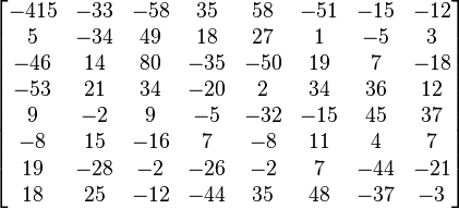
This is an example of DCT coefficient matrix:
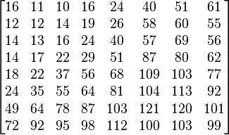
A common quantization matrix is:
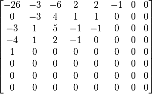
Dividing the DCT coefficient matrix element-wise with this quantization matrix, and rounding to integers results in:
For example, using −415 (the DC coefficient) and rounding to the nearest integer
Typically this process will result in matrices with values primarily in the upper left (low frequency) corner. By using a zig-zag ordering to group the non-zero entries and run length encoding, the quantized matrix can be much more efficiently stored than the non-quantized version.[1]
See also
References
| ||||||||||||||||||||||||||||||||||||||||||||||||||||||


