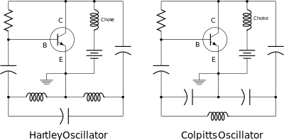
Hartley oscillator
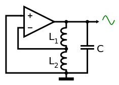
The Hartley oscillator is an electronic oscillator circuit in which the oscillation frequency is determined by a tuned circuit consisting of capacitors and inductors, that is, an LC oscillator. The circuit was invented in 1915 by American engineer Ralph Hartley. The distinguishing feature of the Hartley oscillator is that the tuned circuit consists of a single capacitor in parallel with two inductors in series (or a single tapped inductor), and the feedback signal needed for oscillation is taken from the center connection of the two inductors.
History

The Hartley oscillator was invented by Ralph V.L. Hartley while he was working for the Research Laboratory of the Western Electric Company. Hartley invented and patented the design in 1915 while overseeing Bell System's transatlantic radiotelephone tests; it was awarded patent number 1,356,763 on October 26, 1920. Note that the basic schematic shown below labeled "Common-drain Hartley circuit" is essentially the same as in the patent drawing, except that the tube is replaced by a J-FET, and that the battery for a negative grid bias is not needed.
In 1946 Hartley was awarded the IRE medal of honor "For his early work on oscillating circuits employing triode tubes and likewise for his early recognition and clear exposition of the fundamental relationship between the total amount of information which may be transmitted over a transmission system of limited band-width and the time required."[1](The second half of the citation refers to Hartley's work in information theory which largely paralleled Harry Nyquist.)
Operation

The Hartley oscillator is distinguished by a tank circuit consisting of two series-connected coils (or, often, a tapped coil) in parallel with a capacitor, with an amplifier between the relatively high impedance across the entire LC tank and the relatively low voltage/high current point between the coils. The original 1915 version used a triode as the amplifying device in common plate (cathode follower) configuration, with three batteries, and separate adjustable coils. The simplified circuit shown to the right uses a JFET (in common-drain configuration), an LC tank circuit (here the single winding is tapped) and a single battery. The circuit illustrates the Hartley oscillator operation:
- the output from the JFET's source (emitter, if a BJT had been used; cathode for a triode) has the same phase as the signal at its gate (or base) and roughly the same voltage as its input (which is the voltage across the entire tank circuit), but the current is amplified, i.e. it is acting as a current buffer or voltage-controlled voltage-source.
- this low impedance output is then fed into the coil tapping, effectively into an autotransformer that will step up the voltage, requiring a relatively high current (compared with that available at the top of the coil).
- with the capacitor-coil resonance, all frequencies other than the tuned frequency will tend to be absorbed (the tank will appear as nearly 0Ω near DC due to the inductor's low reactance at low frequencies, and low again at very high frequencies due to the capacitor); they will also shift the phase of the feedback from the 0° needed for oscillation at all but the tuned frequency.
Variations on the simple circuit often include ways to automatically reduce the amplifier gain to maintain a constant output voltage at a level below overload; the simple circuit above will limit the output voltage due to the gate conducting on positive peaks, effectively damping oscillations but not before significant distortion (spurious harmonics) may result. Changing the tapped coil to two separate coils, as in the original patent schematic, still results in a working oscillator but now that the two coils are not magnetically coupled the inductance, and so frequency, calculation has to be modified (see below), and the explanation of the voltage increase mechanism is more complicated than the autotransformer scenario.
A quite different implementation using a tapped coil in an LC tank feedback arrangement, still called a Hartley oscillator (or sometimes "the" Hartley Oscillator circuit[2]) is to employ a common-grid (or common-gate or common-base) amplifier stage, which is still non-inverting but provides voltage gain instead of current gain; the coil tapping is still connected to the cathode (or source or emitter), but this is now the (low impedance) input to the amplifier; the split tank circuit is now dropping the impedance from the relatively high output impedance of the plate (or drain or collector).

The Hartley oscillator is the dual of the Colpitts oscillator which uses a voltage divider made of two capacitors rather than two inductors. Although there is no requirement for there to be mutual coupling between the two coil segments, the circuit is usually implemented using a tapped coil, with the feedback taken from the tap, as shown here. The optimal tapping point (or ratio of coil inductances) depends on the amplifying device used, which may be a bipolar junction transistor, FET, triode, or amplifier of almost any type (non-inverting in this case, although variations of the circuit with an earthed centre-point and feedback from an inverting amplifier or the collector/drain of a transistor are also common), but a junction FET (shown) or triode is often employed as a good degree of amplitude stability (and thus distortion reduction) can be achieved with a simple grid leak resistor-capacitor combination in series with the gate or grid (see the Scott circuit below) thanks to diode conduction on signal peaks building up enough negative bias to limit amplification.

The frequency of oscillation is approximately the resonant frequency of the tank circuit. If the capacitance of the tank capacitor is C and the total inductance of the tapped coil is L then
If two uncoupled coils of inductance L1 and L2 are used then
However, if the two coils are magnetically coupled the total inductance will be greater because of mutual inductance k[3]
The actual oscillation frequency will be slightly lower than given above, because of parasitic capacitance in the coil and loading by the transistor.
Advantages of the Hartley oscillator include:
- The frequency may be adjusted using a single variable capacitor, one side of which can be earthed
- The output amplitude remains constant over the frequency range
- Either a tapped coil or two fixed inductors are needed, and very few other components
- Easy to create an accurate fixed-frequency crystal oscillator variation by replacing the capacitor with a (parallel-resonant) quartz crystal or replacing the top half of the tank circuit with a crystal and grid-leak resistor (as in the Tri-tet oscillator).
Disadvantages include:
- Harmonic-rich output if taken from the amplifier and not directly from the LC circuit (unless amplitude-stabilisation circuitry is employed).
See also
References
- ↑ Ralph V. L. Hartley, Legacies, IEEE History Center, updated January 23, 2003, http://www.ieeeghn.org/wiki/index.php/Ralph_Hartley
- ↑ http://www.learnabout-electronics.org/Oscillators/osc21.php The Hartley Oscillator
- ↑ Jim McLucas, Hartley oscillator requires no coupled inductors, EDN October 26, 2006 http://www.edn.com/article/CA6343253.html
- US 1356763, Hartley, Ralph Vinton Lyon, "Oscillation Generator", published June 1, 1915, issued October 26, 1920
- Langford-Smith, F. (1952), Radiotron Designer's Handbook (4th ed.), Sydney, Australia: Amalgamated Wireless Valve Company Pty., Ltd.
- Record, F. A.; Stiles, J. L. (June 1943), "An Analytical Demonstration of Hartley Oscillator Action", Proceedings of the IRE 31 (6), doi:10.1109/jrproc.1943.230656, ISSN 0096-8390
- Rohde, Ulrich L.; Poddar, Ajay K.; Böck, Georg (May 2005), The Design of Modern Microwave Oscillators for Wireless Applications: Theory and Optimization, New York, NY: John Wiley & Sons, ISBN 0-471-72342-8
- Vendelin, George; Pavio, Anthony M.; Rohde, Ulrich L. (May 2005), Microwave Circuit Design Using Linear and Nonlinear Techniques, New York, NY: John Wiley & Sons, ISBN 0-471-41479-4
External links
- Hartley oscillator, Integrated Publishing
| ||||||||||||||||||||||||||


