Free-space path loss
In telecommunication, free-space path loss (FSPL) is the loss in signal strength of an electromagnetic wave that would result from a line-of-sight path through free space (usually air), with no obstacles nearby to cause reflection or diffraction. It is defined in "Standard Definitions of Terms for Antennas", IEEE Std 145-1983, as "The loss between two isotropic radiators in free space, expressed as a power ratio." Usually it is expressed in dB, although the IEEE standard does not say that. So it assumes that the antenna gain is a power ratio of 1.0, or 0 dB. It does not include any loss associated with hardware imperfections, or the effects of any antennas gain. A discussion of these losses may be found in the article on link budget. The FSPL is rarely used standalone, but rather as a part of the Friis transmission equation, which includes the gain of antennas.
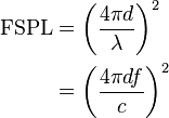
Free-space path loss formula
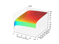
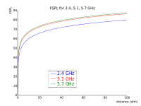
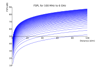
Free-space path loss is proportional to the square of the distance between the transmitter and receiver, and also proportional to the square of the frequency of the radio signal.
The equation for FSPL is
where:
 is the signal wavelength (in metres),
 is the signal frequency (in hertz),
 is the distance from the transmitter (in metres),
 is the speed of light in a vacuum, 2.99792458 × 10⁸ metres per second.
This equation is only accurate in the far field where spherical spreading can be assumed; it does not hold close to the transmitter.
Free-space path loss in decibels
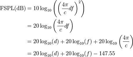
A convenient way to express FSPL is in terms of dB:
where the units are as before.
For typical radio applications, it is common to find  measured in units of GHz and
  in km, in which case the FSPL equation becomes
For  in meters and kilohertz, respectively, the constant becomes
  .
.
For  in meters and megahertz, respectively, the constant becomes
  .
.
For  in kilometers and megahertz, respectively, the constant becomes
  .
.
Physical explanation
The FSPL expression above often leads to the erroneous belief that free space attenuates an electromagnetic wave according to its frequency. This is not the case, as there is no physical mechanism that could cause this. The expression for FSPL actually encapsulates two effects.
Distance dependency
Dependency of the FSPL on distance is caused by the spreading out of electromagnetic energy in free space and is described by the inverse square law, i.e.
where:
-
 is the power per unit area or power spatial density (in watts per metre-squared) at distance
  ,
, -
 is the equivalent isotropically radiated power (in watts).
Note that this is not a frequency-dependent effect.
Frequency dependency
The frequency dependency is somewhat more confusing. The question is often asked: Why should path loss, which is just a geometric inverse-square loss, be a function of frequency? The answer is that path loss is defined on the use of an isotropic receiving antenna ( ).[1]:sec. 5.3.3, p. 256 This can be seen if we derive the FSPL from the Friis transmission equation.
Hence path loss is a convenient tool; it represents a hypothetical received-power loss that would occur if the receiving antenna were isotropic. Therefore, the FSPL can be viewed as a convenient collection of terms that have been assigned the unfortunate name path loss. This name calls up an image of purely geometric effect and fails to emphasize the requirement that  . A better choice of the name would have been unity-gain propagation loss.[1]:sec. 5.3.3, p. 256
Hence frequency dependency of the path loss is caused by the frequency dependency of the receiving antenna's aperture in case the antenna gain is fixed. Antenna aperture in turn determines how well an antenna can pick up power from an incoming electromagnetic wave.
Dependency of antenna aperture from antenna gain is described by the formula:[2]:Chap3, p. 22,(3.52)
This formula represents a well-known fact, that the lower the frequency (the longer the wavelength), the bigger antenna is needed to achieve certain antenna gain. Therefore, for a theoretical isotropic antenna ( ), the received power
  is described by a formula:
where  is a power density of an electromagnetic wave at a location of theoretical isotropic receiving antenna. Note that this is entirely dependent on wavelength, which is how the frequency-dependent behaviour arises.
In simple terms the frequency dependency of the path loss can be explained like this: with the increase of the frequency the requirement to keep the gain of the receiving antenna intact will cause an antenna aperture to be decreased, which will result in less energy being captured with the smaller antenna, which is similar to increasing the path loss in the situation when receiving antenna gain would not have been fixed.
See also
Further reading
- C.A. Balanis, "Antenna Theory", 2003, John Wiley and Sons Inc.
External links
- Derivation of the dB version of the Path Loss Equation
- Propagation Models Chapter on Free Space Propagation
- Path loss Pages for free space and real world - includes free space loss calculator
References
- 1 2 Bernard Sklar (December 2005). Digital Communications: Fundamentals & Applications, Second Edition. Bernard Goodwin. ISBN 0-13-084788-7.
- ↑ Prof. Robert A. York. "course ECE 201C - Antenna Theory". University of California in Santa Barbara.
