Fracture
| ||||||
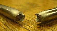
A fracture is the separation of an object or material into two or more pieces under the action of stress. The fracture of a solid usually occurs due to the development of certain displacement discontinuity surfaces within the solid. If a displacement develops perpendicular to the surface of displacement, it is called a normal tensile crack or simply a crack; if a displacement develops tangentially to the surface of displacement, it is called a shear crack, slip band, or dislocation.[1] Fracture strength or breaking strength is the stress when a specimen fails or fractures.
The word fracture is often applied to bones of living creatures (that is, a bone fracture), or to crystals or crystalline materials, such as gemstones or metal. Sometimes, in crystalline materials, individual crystals fracture without the body actually separating into two or more pieces. Depending on the substance which is fractured, a fracture reduces strength (most substances) or inhibits transmission of light (optical crystals). A detailed understanding of how fracture occurs in materials may be assisted by the study of fracture mechanics.
A fracture is also the term used for a particular mask data preparation procedure within the realm of integrated circuit design that involves transposing complex polygons into simpler shapes such as trapezoids and rectangles.
Fracture strength

1. Ultimate tensile strength
2. Yield strength
3. Proportional limit stress
4. Fracture
5. Offset strain (typically 0.2%)
Fracture strength, also known as breaking strength, is the stress at which a specimen fails via fracture.[2] This is usually determined for a given specimen by a tensile test, which charts the stress-strain curve (see image). The final recorded point is the fracture strength.
Ductile materials have a fracture strength lower than the ultimate tensile strength (UTS), whereas in brittle materials the fracture strength is equivalent to the UTS.[2] If a ductile material reaches its ultimate tensile strength in a load-controlled situation,[Note 1] it will continue to deform, with no additional load application, until it ruptures. However, if the loading is displacement-controlled,[Note 2] the deformation of the material may relieve the load, preventing rupture.
If the stress-strain curve is plotted in terms of true stress and true strain the curve will always slope upwards and never reverse, as true stress is corrected for the decrease in cross-sectional area. The true stress on the material at the time of rupture is known as the breaking strength. This is the maximum stress on the true stress-strain curve.
Types
Brittle fracture


In brittle fracture, no apparent plastic deformation takes place before fracture. In brittle crystalline materials, fracture can occur by cleavage as the result of tensile stress acting normal to crystallographic planes with low bonding (cleavage planes). In amorphous solids, by contrast, the lack of a crystalline structure results in a conchoidal fracture, with cracks proceeding normal to the applied tension. The sinking of RMS Titanic in 1912 from an iceberg collision is widely reported to have been due to brittle fracture of the hull's steel plates.[3]
The theoretical strength of a crystalline material is (roughly)
where: -
 is the Young's modulus of the material,
 is the surface energy, and
 is the equilibrium distance between atomic centers.
On the other hand, a crack introduces a stress concentration modeled by
 (For sharp cracks)
where: -
 is the loading stress,
 is half the length of the crack, and
 is the radius of curvature at the crack tip.
Putting these two equations together, we get
Looking closely, we can see that sharp cracks (small  ) and large defects (large
  ) both lower the fracture strength of the material.
Recently, scientists have discovered supersonic fracture, the phenomenon of crack motion faster than the speed of sound in a material.[4] This phenomenon was recently also verified by experiment of fracture in rubber-like materials.
Brittle fracture may be avoided by limiting pressure and temperature within limits. Each system has a brittle fracture prevention limit curve defined by the weakest components at given temperatures and pressures allowing for the largest undetected preexisting flaw in each component.
Ductile fracture

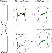
In ductile fracture, extensive plastic deformation (necking) takes place before fracture. The terms rupture or ductile rupture describe the ultimate failure of tough ductile materials loaded in tension. Rather than cracking, the material "pulls apart," generally leaving a rough surface. In this case there is slow propagation and an absorption of a large amount energy before fracture.

Many ductile metals, especially materials with high purity, can sustain very large deformation of 50–100% or more strain before fracture under favorable loading condition and environmental condition. The strain at which the fracture happens is controlled by the purity of the materials. At room temperature, pure iron can undergo deformation up to 100% strain before breaking, while cast iron or high-carbon steels can barely sustain 3% of strain.
Because ductile rupture involves a high degree of plastic deformation, the fracture behavior of a propagating crack as modelled above changes fundamentally. Some of the energy from stress concentrations at the crack tips is dissipated by plastic deformation before the crack actually propagates.
The basic steps are: void formation, void coalescence (also known as crack formation), crack propagation, and failure, often resulting in a cup-and-cone shaped failure surface.
Crack separation modes
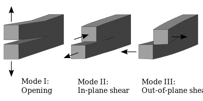
There are three ways of applying a force to enable a crack to propagate:

- Mode I crack – Opening mode (a tensile stress normal to the plane of the crack)
- Mode II crack – Sliding mode (a shear stress acting parallel to the plane of the crack and perpendicular to the crack front)
- Mode III crack – Tearing mode (a shear stress acting parallel to the plane of the crack and parallel to the crack front)
Crack initiation and propagation accompany fracture. The manner through which the crack propagates through the material gives great insight into the mode of fracture. In ductile materials (ductile fracture), the crack moves slowly and is accompanied by a large amount of plastic deformation. The crack will usually not extend unless an increased stress is applied. On the other hand, in dealing with brittle fracture, cracks spread very rapidly with little or no plastic deformation. The cracks that propagate in a brittle material will continue to grow and increase in magnitude once they are initiated. Another important mannerism of crack propagation is the way in which the advancing crack travels through the material. A crack that passes through the grains within the material is undergoing transgranular fracture. However, a crack that propagates along the grain boundaries is termed an intergranular fracture.
See also
- Environmental stress fracture
- Fracture (mineralogy)
- Fracture (geology)
- Fractography
- Forensic engineering
- Forensic materials engineering
- Gilbert tessellation
- Microvoid coalescence
Notes
- ↑ A simple load-controlled tensile situation would be to support a specimen from above, and hang a weight from the bottom end. The load on the specimen is then independent of its deformation.
- ↑ A simple displacement-controlled tensile situation would be to attach a very stiff jack to the ends of a specimen. As the jack extends, it controls the displacement of the specimen; the load on the specimen is dependent on the deformation.
References
- ↑ Cherepanov, G.P., Mechanics of Brittle Fracture
- 1 2 Degarmo, E. Paul; Black, J T.; Kohser, Ronald A. (2003), Materials and Processes in Manufacturing (9th ed.), Wiley, p. 32, ISBN 0-471-65653-4.
- ↑
- ↑ C. H. Chen, H. P. Zhang, J. Niemczura, K. Ravi-Chandar and M. Marder (November 2011). "Scaling of crack propagation in rubber sheets". Europhysics Letters 96 (3): 36009. Bibcode:2011EL.....9636009C. doi:10.1209/0295-5075/96/36009.
Further reading
- Dieter, G. E. (1988) Mechanical Metallurgy ISBN 0-07-100406-8
- A. Garcimartin, A. Guarino, L. Bellon and S. Cilberto (1997) " Statistical Properties of Fracture Precursors ". Physical Review Letters, 79, 3202 (1997)
- Callister, Jr., William D. (2002) Materials Science and Engineering: An Introduction. ISBN 0-471-13576-3
- Peter Rhys Lewis, Colin Gagg, Ken Reynolds, CRC Press (2004), Forensic Materials Engineering: Case Studies.
External links
- Web postings at http://www.jwave.vt.edu/crcd/farkas/lectures/Fract1/tsld006.htm
- Virtual museum of failed products at http://materials.open.ac.uk/mem/index.html
- Fracture and Reconstruction of a Clay Bowl
- Ductile fracture
- Modes of Fracture from Virginia Tech Materials Science and Engineering
|

