Flap (aeronautics)

Flaps are devices used to alter the lift characteristics of a wing and are mounted on the trailing edges of the wings of a fixed-wing aircraft to reduce the speed at which the aircraft can be safely flown and to increase the angle of descent for landing. They do this by lowering the stall speed and increasing the drag. Flaps shorten takeoff and landing distances.
Extending flaps increases the camber or curvature of the wing, raising the maximum lift coefficient — the lift a wing can generate. This allows the aircraft to generate as much lift, but at a lower speed, reducing the stalling speed of the aircraft, or the minimum speed at which the aircraft will maintain flight. Extending flaps increases drag, which can be beneficial during approach and landing, because it slows the aircraft. On some aircraft, a useful side effect of flap deployment is a decrease in aircraft pitch angle which lowers the nose thereby improving the pilot's view of the runway over the nose of the aircraft during landing. However the flaps may also cause pitch-up depending on the type of flap and the location of the wing.
There are many different types of flaps used, with the specific choice depending on the size, speed and complexity of the aircraft on which they are to be used, as well as the era in which the aircraft was designed. Plain flaps, slotted flaps, and Fowler flaps are the most common. Krueger flaps are positioned on the leading edge of the wings and are used on many jet airliners.
The Fowler, Fairey-Youngman and Gouge types of flap increase the wing area in addition to changing the camber. The larger lifting surface reduces wing loading and allows the aircraft to generate the required lift at a lower speed and reduces stalling speed.
Physics explanation
The general airplane lift equation demonstrates these relationships:[1]
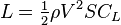
where:
- L is the amount of Lift produced,
-
 is the air density,
 - V is the true airspeed of the airplane or the Velocity of the airplane, relative to the air
- S is the wing area and
-
 is the lift coefficient, which is determined by the shape of the airfoil used and the angle at which the wing meets the air (or angle of attack).
Here, it can be seen that increasing the area (S) and lift coefficient () allow a similar amount of lift to be generated at a lower airspeed (V).

Extending the flaps also increases the drag coefficient of the aircraft. Therefore, for any given weight and airspeed, flaps increase the drag force. Flaps increase the drag coefficient of an aircraft due to higher induced drag caused by the distorted spanwise lift distribution on the wing with flaps extended. Some flaps increase the wing area and, for any given speed, this also increases the parasitic drag component of total drag.[1]
Flaps during takeoff
Depending on the aircraft type, flaps may be partially extended for takeoff.[1] When used during takeoff, flaps trade runway distance for climb rate—using flaps reduces ground roll and the climb rate. The amount of flap used on takeoff is specific to each type of aircraft, and the manufacturer will suggest limits and may indicate the reduction in climb rate to be expected. The Cessna 172S Pilot Operating Handbook generally recommends 10° of flaps on takeoff, especially when the ground is rough or soft.[2]
Flaps during landing

Flaps may be fully extended for landing to give the aircraft a lower stall speed so the approach to landing can be flown more slowly, which also allows the aircraft to land in a shorter distance. The higher lift and drag associated with fully extended flaps allows a steeper and slower approach to the landing site, but imposes handling difficulties in aircraft with very low wing loading (the ratio between the wing area and the weight of the aircraft). Winds across the line of flight, known as crosswinds, cause the windward side of the aircraft to generate more lift and drag, causing the aircraft to roll, yaw and pitch off its intended flight path, and as a result many light aircraft land with reduced flap settings in crosswinds. Furthermore, once the aircraft is on the ground, the flaps may decrease the effectiveness of the brakes since the wing is still generating lift and preventing the entire weight of the aircraft from resting on the tires, thus increasing stopping distance, particularly in wet or icy conditions. Usually, the pilot will raise the flaps as soon as possible to prevent this from occurring.[2]
Maneuvering flaps
Some gliders not only use flaps when landing, but also in flight to optimize the camber of the wing for the chosen speed. When thermalling, flaps may be partially extended to reduce the stalling speed so that the glider can be flown more slowly and thereby reduce the rate of sink, which lets the glider use the rising air of the thermal more efficiently, and to turn in a smaller circle to make best use of the core of the thermal. At higher speeds a negative flap setting is used to reduce the nose-down pitching moment. This reduces the balancing load required on the horizontal stabilizer, which in turn reduces the trim drag associated with keeping the glider in longitudinal trim. Negative flap may also be used during the initial stage of an aerotow launch and at the end of the landing run in order to maintain better control by the ailerons.
Like gliders, some fighters such as the Nakajima Ki-43 also use special flaps to improve maneuverability during air combat, allowing the fighter to create more lift at a given speed, allowing for much tighter turns.[3] The flaps used for this must be designed specifically to handle the greater stresses and most flaps have a maximum speed at which they can be deployed. Control line model aircraft built for precision aerobatics competition usually have a type of maneuvering flap system that moves them in an opposing direction to the elevators, to assist in tightening the radius of a maneuver.
Flap track fairings
Fairings streamline the airflow over the flap support mechanisms to help reduce cruise drag - the smaller the fairing the lower the drag.[4]
Thrust gates
Thrust gates, or gaps, in the trailing edge flaps may be required to minimise interference between the engine flow and deployed flaps. In the absence of an in-board aileron, which provides a gap in many flap installations, a modified flap section may be needed. The thrust gate on the Boeing 757 was provided by a single-slotted flap in between the inboard and outboard double-slotted flaps.[5] The A320,A330,A340 and A380 have no in-board aileron. No thrust gate is required in the continuous, single-slotted flap. Interference in the go-around case while the flaps are still fully deployed can cause increased drag which must not compromise the climb gradient.[6]
Types

- Plain flap: the rear portion of airfoil rotates downwards on a simple hinge mounted at the front of the flap.[7] The Royal Aircraft Factory and National Physical Laboratory in the United Kingdom tested flaps in 1913 and 1914, but these were never installed in an actual aircraft.[8] In 1916, the Fairey Aviation Company made a number of improvements to a Sopwith Baby they were rebuilding, including their Patent Camber Changing Gear, making the Fairey Hamble Baby as they renamed it, the first aircraft to fly with flaps.[8] These were full span plain flaps which incorporated ailerons, making it also the first instance of flaperons.[8] Fairey were not alone however, as Breguet soon incorporated automatic flaps into the lower wing of their Breguet 14 reconnaissance/bomber in 1917.[9] Due to the greater efficiency of other flap types, the plain flap is normally only used where simplicity is required.
.png)
- Split flap: the rear portion of the lower surface of the airfoil hinges downwards from the leading edge of the flap, while the upper surface stays immobile.[10] Like the plain flap, this can cause large changes in longitudinal trim, pitching the nose either down or up, and tends to produce more drag than lift. At full deflection, a split flaps acts much like a spoiler, producing lots of drag and little or no lift. It was invented by Orville Wright and James M. H. Jacobs in 1920, but only became common in the 1930s and was then quickly superseded. The Douglas DC-3 & C-47 used a split flap.
- Slotted flap: a gap between the flap and the wing forces high pressure air from below the wing over the flap helping the airflow remain attached to the flap, increasing lift compared to a split flap.[11] Additionally, lift across the entire chord of the primary airfoil is greatly increased as the velocity of air leaving its trailing edge is raised, from the typical non-flap 80% of freestream, to that of the higher-speed, lower-pressure air flowing around the leading edge of the slotted flap.[12] Any flap that allows air to pass between the wing and the flap is considered a slotted flap. The slotted flap was a result of research at Handley-Page, a variant of the slot that dates from the 1920s, but wasn't widely used until much later. Some flaps use multiple slots to further boost the effect.
- Fowler flap: split flap that slides backward flat, before hinging downward, thereby increasing first chord, then camber.[13] The flap may form part of the upper surface of the wing, like a plain flap, or it may not, like a split flap, but it must slide rearward before lowering. It may provide some slot effect, but this is not a defining feature of the type.[14] Invented by Harlan D. Fowler in 1924, and tested by Fred Weick at NACA in 1932. They were first used on the Martin 146 prototype in 1935, and in production on the 1937 Lockheed Electra,[15] and are still in widespread use on modern aircraft, often with multiple slots.
- Junkers flap: a slotted plain flap where the flap is fixed below the trailing edge of the wing, rotating about its forward edge, and usually forming the "inboard" hinged section (closer to the root) of the Junkers Doppelflügel, or "double-wing" style of wing trailing edge control surfaces (including the outboard-mounted ailerons), which hung just below and behind the wing's fixed trailing edge.[16] When not in use, it has more drag than other types, but is more effective at creating additional lift than a plain or split flap, while retaining their mechanical simplicity. Invented by Otto Mader at Junkers in the late 1920s, they were historically most often seen on both the Ju 52/3m airliner/cargo plane, and the Ju 87 Stuka dive bomber, though the same wing control surface can be also be found on many modern ultralights.
- Gouge flap: a type of split flap that slides backward along curved tracks that force the trailing edge downward, increasing chord and camber without affecting trim or requiring any additional mechanisms.[17] It was invented by Arthur Gouge for Short Brothers in 1936 and used on the Short Empire and Sunderland flying boats, which used the very thick Shorts A.D.5 airfoil. Short Brothers may have been the only company to use this type.
- Fairey-Youngman flap: drops down (becoming a Junkers Flap) before sliding aft and then rotating up or down. Fairey was one of the few exponents of this design, which was used on the Fairey Firefly and Fairey Barracuda. When in the extended position, it could be angled up (to a negative angle of incidence) so that the aircraft could be dived vertically without needing excessive trim changes.
- Zap Flap or commonly, but incorrectly, Zapp Flap: Invented by Edward F. Zaparka while he was with Berliner/Joyce and tested on a General Aircraft Corporation Aristocrat in 1932 and on other types periodically thereafter, but it saw little use on production aircraft other than on the Northrop P-61 Black Widow. The leading edge of the flap is mounted on a track, while a point at mid chord on the flap is connected via an arm to a pivot just above the track. When the flap's leading edge moves aft along the track, the triangle formed by the track, the shaft and the surface of the flap (fixed at the pivot) gets narrower and deeper, forcing the flap down.[18]
- Krueger flap: hinged flap, which folds out from under the wing's leading edge while not forming a part of the leading edge of the wing when retracted. This increases the camber and thickness of the wing, which in turn increases lift and drag.[19][20] This is not the same as a leading edge droop flap, as that is formed from the entire leading edge.[21] Invented by Werner Krüger in 1943 and evaluated in Goettingen,[22] Krueger flaps are found on many modern swept wing airliners.
- Gurney flap: A small fixed perpendicular tab of between 1 and 2% of the wing chord, mounted on the high pressure side of the trailing edge of an airfoil. It was named for racing car driver Dan Gurney who rediscovered it in 1971, and has since been used on some helicopters such as the Sikorsky S-76B to correct control problems without having to resort to a major redesign. It boosts the efficiency of even basic theoretical airfoils (made up of a triangle and a circle overlapped) to the equivalent of a conventional airfoil. The principle was discovered in the 1930s, but was rarely used and was then forgotten. Late marks of the Supermarine Spitfire used a bead on the trailing edge of the elevators, which functioned in a similar manner.
- Leading edge droop: entire leading edge of the wing rotating downward,[23] effectively increasing camber, but slightly reducing chord. Most commonly found on fighters with very thin wings unsuited to other leading edge high lift devices.
- Blown flaps: also known as Boundary Layer Control Systems, are systems that blow engine air or exhaust over the flaps to increase lift beyond that attainable with mechanical flaps. Types include the original (internally blown flap) which blows compressed air from the engine over the top of the flap, the externally blown flap, which blows engine exhaust over the upper and lower surfaces of the flap, and upper surface blowing which blows engine exhaust over the top of the wing and flap. While testing was done in Britain and Germany before the Second World War,[24] and flight trials started, the first production aircraft with blown flaps wasn't until the 1957 Lockheed T2V SeaStar.[25] Upper Surface Blowing was used on the Boeing YC-14 in 1976.
- Flexible flap or FlexFoil: modern interpretation of wing warping, internal mechanical actuators bend a lattice that changes the airfoil shape. It may have a flexible gap seal at the transition between fixed and flexible airfoils.[26]
- Flaperon: a type of aircraft control surface that combines aspects of both flaps and ailerons.
- Controls that look like flaps, but are not:
- Handley Page leading edge slats/slots may be confused for flaps, but are mounted on the top of the wings' leading edge and while they may be either fixed or retractable, when deployed they provide a slot or gap under the slat to force air against the top of the wing, which is absent on a Krueger flap. They offer excellent lift and enhance controllability at low speeds. Other types of flaps may be equipped with one or more slots to increase their effectiveness, a typical setup on many modern airliners. These are known as slotted flaps as described above. Frederick Handley Page experimented with fore and aft slot designs in the 20s and 30s.
- Spoilers may also be confused for flaps, but are intended to create drag and reduce lift by "spoiling" the airflow over the wing. A spoiler is much larger than a Gurney flap, and can be retracted. Spoilers are usually installed mid chord on the upper surface of the wing, but may also be installed on the lower surface of the wing as well.
- Air brakes are used on high performance combat aircraft to increase drag, allowing the aircraft to decelerate rapidly. They may be installed either on the wings or fuselage and differ from flaps and spoilers in that they are not intended to reduce lift and are built strongly enough to be deployed at much higher speeds.
- Ailerons are similar to flaps (and work the same way), but are intended to provide lateral control, rather than to change the lifting characteristics of both wings together, and so operate differentially - when an aileron on one wing increases the lift, the opposite aileron does not, and will often work to decrease lift. Some aircraft use flaperons, which combine both the functionality of flaps and ailerons in a single control, working together to increase lift, but to slightly different degrees so the aircraft will roll toward the side generating the least lift. Flaperons were used by the Fairey Aviation Company as early as 1916, but didn't become common until after World War II.
-

Split flap on a World War II Avro Lancaster bomber
-

Fully extended double slotted Fowler flaps before landing on a Boeing 737
-

Triple-slotted trailing-edge flaps and leading edge Krueger flaps fully extended on a Boeing 747 for landing.
-

Junkers flaps, doubling as ailerons clearly visible on a Kitfox Lite
-
_arrives_London_Heathrow_17Oct2010_arp.jpg)
The triple-slotted trailing edge flaps on an Air New Zealand Boeing 747-400 (2010)
See also
| Wikimedia Commons has media related to Trailing-edge flaps. |
- Air brake (aeronautics)
- Aircraft flight control system
- Aileron
- Circulation control wing
- High-lift device
- Leading-edge slats
References
- 1 2 3 Perkins, Courtland; Hage, Robert (1949). Airplane performance, stability and control, Chapter 2, John Wiley and Sons. ISBN 0-471-68046-X.
- 1 2 Cessna Aircraft Company. Cessna Model 172S Nav III. Revision 3 - 12, 2006, p. 4-19 to 4-47.
- ↑ Windrow, 1965, p.4
- ↑ http://ntrs.nasa.gov/archive/nasa/casi.ntrs.nasa.gov/19960052267.pdf p.39
- ↑ http://ntrs.nasa.gov/archive/nasa/casi.ntrs.nasa.gov/19960052267.pdf p.40,54
- ↑ http://citeseerx.ist.psu.edu/viewdoc/download?doi=10.1.1.602.7484&rep=rep1&type=pdf p.7
- ↑ Gunston, Bill, The Cambridge Aerospace Dictionary Cambridge, Cambridge University Press 2004, ISBN 978-0-521-84140-5/ISBN 0-521-84140-2 p.452
- 1 2 3 Taylor, 1974, pp.8-9
- ↑ Toelle, Alan (2003). Windsock Datafile Special, Breguet 14. Hertfordshire, Great Britain: Albatros Productions. ISBN 1-902207-61-0.
- ↑ Gunston, Bill, The Cambridge Aerospace Dictionary Cambridge, Cambridge University Press 2004, ISBN 978-0-521-84140-5/ISBN 0-521-84140-2 p.584
- ↑ Gunston, Bill, The Cambridge Aerospace Dictionary Cambridge, Cambridge University Press 2004, ISBN 978-0-521-84140-5/ISBN 0-521-84140-2 p.569
- ↑ Smith, Apollo M. O. (1975). "High-Lift Aerodynamics" (PDF). Journal of Aircraft 12 (6): 518–523. doi:10.2514/3.59830. ISSN 0021-8669. Retrieved 12 July 2011.
- ↑ Gunston, Bill, The Cambridge Aerospace Dictionary, Cambridge, Cambridge University Press 2004, ISBN 978-0-521-84140-5/ISBN 0-521-84140-2 p.249-250
- ↑ Flight 1942
- ↑ National Aeronautics and Space Administration. Wind and Beyond: A Documentary Journey Into the History of Aerodynamics.
- ↑ Gunston, Bill, The Cambridge Aerospace Dictionary, Cambridge, Cambridge University Press 2004, ISBN 978-0-521-84140-5/ISBN 0-521-84140-2 p.331
- ↑ Gunston, Bill, The Cambridge Aerospace Dictionary, Cambridge, Cambridge University Press 2004, ISBN 978-0-521-84140-5/ISBN 0-521-84140-2 p.270
- ↑ C.M. Poulsen, ed. (27 July 1933). ""The Aircraft Engineer - flight engineering section" Supplement to Flight". Flight Magazine. pp. 754a–d.
- ↑ NASA on High-Lift Systems
- ↑ Virginia Tech – Aerospace & Ocean Engineering
- ↑ Gunston, Bill, The Cambridge Aerospace Dictionary Cambridge, Cambridge University Press 2004, ISBN 978-0-521-84140-5/ISBN 0-521-84140-2 p.335
- ↑ from German wiki page on Krüger flaps @ http://wikipedia.qwika.com/de2en/Kr%C3%BCgerklappe (accessed 18 October 2011)
- ↑ Gunston, Bill, The Cambridge Aerospace Dictionary Cambridge, Cambridge University Press 2004, ISBN 978-0-521-84140-5/ISBN 0-521-84140-2 p.191
- ↑ http://naca.central.cranfield.ac.uk/reports/arc/cp/0209.pdf page 1 accessdate=11 Jan 2016
- ↑ American Military Training Aircraft' E.R. Johnson and Lloyd S. Jones, McFarland & Co. Inc. Publishers, Jefferson, North Carolina
- ↑ "Shape-shifting flap takes flight". Retrieved 19 November 2014.
Further reading
- Clancy, L.J. (1975). "6". Aerodynamics. London: Pitman Publishing Limited. ISBN 0-273-01120-0.
- Taylor, H.A. (1974). Fairey Aircraft since 1915. London: Putnam. ISBN 0-370-00065-X.
- Windrow, Martin C. and René J. Francillon. The Nakajima Ki-43 Hayabusa. Leatherhead, Surrey, UK: Profile Publications, 1965.
| ||||||||||||||||||||||||||||||||||