Foster's reactance theorem
Foster's reactance theorem is an important theorem in the fields of electrical network analysis and synthesis. The theorem states that the reactance of a passive, lossless two-terminal (one-port) network always strictly monotonically increases with frequency. It is easily seen that the reactances of inductors and capacitors individually increase with frequency and from that basis a proof for passive lossless networks generally can be constructed. The proof of the theorem was presented by Ronald Martin Foster in 1924, although the principle had been published earlier by Foster's colleagues at American Telephone & Telegraph.
The theorem can be extended to admittances and the encompassing concept of immittances. A consequence of Foster's theorem is that poles and zeroes of the reactance must alternate with frequency. Foster used this property to develop two canonical forms for realising these networks. Foster's work was an important starting point for the development of network synthesis.
It is possible to construct non-Foster networks using active components such as amplifiers. These can generate an impedance equivalent to a negative inductance or capacitance. The negative impedance converter is an example of such a circuit.
Explanation
Reactance is the imaginary part of the complex electrical impedance. Both capacitors and inductors possess reactance (but of opposite sign) and are frequency dependent. The specification that the network must be passive and lossless implies that there are no resistors (lossless), or amplifiers or energy sources (passive) in the network. The network consequently must consist entirely of inductors and capacitors and the impedance will be purely an imaginary number with zero real part. Foster's theorem applies equally to the admittance of a network, that is the susceptance (imaginary part of admittance) of a passive, lossless one-port monotonically increases with frequency. This result may seem counterintuitive since admittance is the reciprocal of impedance, but is easily proved. If the impedance is
where  is reactance and
  is the imaginary unit, then the admittance is given by
where  is susceptance.
If X is monotonically increasing with frequency then 1/X must be monotonically decreasing. −1/X must consequently be monotonically increasing and hence it is proved that B is increasing also.
It is often the case in network theory that a principle or procedure applies equally well to impedance or admittance—reflecting the principle of duality for electric networks. It is convenient in these circumstances to use the concept of immittance, which can mean either impedance or admittance. The mathematics is carried out without specifying units until it is desired to calculate a specific example. Foster's theorem can thus be stated in a more general form as,
- Foster's theorem (immittance form)
- The imaginary immittance of a passive, lossless one-port strictly monotonically increases with frequency.
Foster's theorem is quite general. In particular, it applies to distributed element networks, although Foster formulated it in terms of discrete inductors and capacitors. It is therefore applicable at microwave frequencies just as much as it is at lower frequencies.[1][2]
Examples
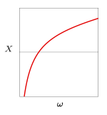
 Plot of the reactance of an inductor against frequency |
 Plot of the reactance of a capacitor against frequency |
 Plot of the reactance of a series LC circuit against frequency |
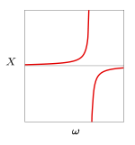
 Plot of the reactance of a parallel LC circuit against frequency |
The following examples illustrate this theorem in a number of simple circuits.
Inductor
The impedance of an inductor is given by,
 is inductance
 is angular frequency
so the reactance is,
which by inspection can be seen to be monotonically (and linearly) increasing with frequency.[3]
Capacitor
The impedance of a capacitor is given by,
 is capacitance
so the reactance is,
which again is monotonically increasing with frequency. The impedance function of the capacitor is identical to the admittance function of the inductor and vice versa. It is a general result that the dual of any immittance function that obeys Foster's theorem will also follow Foster's theorem.[3]
Series resonant circuit
A series LC circuit has an impedance that is the sum of the impedances of an inductor and capacitor,
At low frequencies the reactance is dominated by the capacitor and so is large and negative. This monotonically increases towards zero (the magnitude of the capacitor reactance is becoming smaller). The reactance passes through zero at the point where the magnitudes of the capacitor and inductor reactances are equal (the resonant frequency) and then continues to monotonically increase as the inductor reactance becomes progressively dominant.[4]
Parallel resonant circuit
A parallel LC circuit is the dual of the series circuit and hence its admittance function is the same form as the impedance function of the series circuit,
The impedance function is,
At low frequencies the reactance is dominated by the inductor and is small and positive. This monotonically increases towards a pole at the anti-resonant frequency where the susceptance of the inductor and capacitor are equal and opposite and cancel. Past the pole the reactance is large and negative and increasing towards zero where it is dominated by the capacitance.[4]
Poles and zeroes

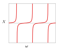
A consequence of Foster's theorem is that the poles and zeroes of any passive immittance function must alternate as frequency increases. After passing through a pole the function will be negative and is obliged to pass through zero before reaching the next pole if it is to be monotonically increasing.[1]
The poles and zeroes of an immittance function completely determine the frequency characteristics of a Foster network. Two Foster networks that have identical poles and zeroes will be equivalent circuits in the sense that their immittance functions will be identical. There can be a scaling factor difference between them (all elements of the immitance multiplied by the same scaling factor) but the shape of the two immitance functions will be identical.[5]
Another consequence of Foster's theorem is that the phase of an immitance must monatonically increase with frequency. Consequently, the plot of a Foster immittance function on a Smith chart must always travel around the chart in a clockwise direction with increasing frequency.[2]
Realisation


A one-port passive immittance consisting of discrete elements (that is, not a distributed element circuit) can be represented as a rational function of s,
- where,
 is immittance
 are polynomials with real, positive coefficiencts
 is the Laplace transform variable, which can be replaced with
  when dealing with steady-state AC signals.
This follows from the fact the impedance of L and C elements are themselves simple rational functions and any algebraic combination of rational functions results in another rational function.
This is sometimes referred to as the driving point impedance because it is the impedance at the place in the network at which the external circuit is connected and "drives" it with a signal. In his paper, Foster describes how such a lossless rational function may be realised in two ways. Foster's first form consists of a number of series connected parallel LC circuits. Foster's second form of driving point impedance consists of a number of parallel connected series LC circuits. The realisation of the driving point impedance is by no means unique. Foster's realisation has the advantage that the poles and/or zeroes are directly associated with a particular resonant circuit, but there are many other realisations. Perhaps the most well known is Cauer's ladder realisation from filter design.[6][7][8]
Non-Foster networks
A Foster network must be passive, so an active network, containing a power source, may not obey Foster's theorem. These are called non-Foster networks.[9] In particular, circuits containing an amplifier with positive feedback can have reactance which declines with frequency. For example, it is possible to create negative capacitance and inductance with negative impedance converter circuits. These circuits will have an immittance function with a phase of ±π/2 like a positive reactance but a reactance amplitude with a negative slope against frequency.[6]
These are of interest because they can accomplish tasks a Foster network cannot. For example, the usual passive Foster impedance matching networks can only match the impedance of an antenna with a transmission line at discrete frequencies, which limits the bandwidth of the antenna. A non-Foster network could match an antenna over a continuous band of frequencies.[9] This would allow the creation of compact antennas that have wide bandwidth, violating the Chu-Harrington limit. Practical non-Foster networks are an active area of research.
History
The theorem was developed at American Telephone & Telegraph as part of ongoing investigations into improved filters for telephone multiplexing applications. This work was commercially important; large sums of money could be saved by increasing the number of telephone conversations that could be carried on one line.[10] The theorem was first published by Campbell in 1922 but without a proof.[11] Great use was immediately made of the theorem in filter design, it appears prominently, along with a proof, in Zobel's landmark paper of 1923 which summarised the state of the art of filter design at that time.[12] Foster published his paper the following year which included his canonical realisation forms.[13]
Cauer in Germany grasped the importance of Foster's work and used it as the foundation of network synthesis. Amongst Cauer's many innovations was the extension of Foster's work to all 2-element-kind networks after discovering an isomorphism between them. Cauer was interested in finding the necessary and sufficient condition for realisability of a rational one-port network from its polynomial function, a condition now known to be a positive-real function, and the reverse problem of which networks were equivalent, that is, had the same polynomial function. Both of these were important problems in network theory and filter design. Foster networks are only a subset of realisable networks,[14]
References
- 1 2 Aberle and Loepsinger-Romak, pp.8-9.
- 1 2 Radmanesh, p.459.
- 1 2 Cherry, pp.100-101.
- 1 2 Cherry, pp.100-102.
- ↑ Smith and Alley, p.173.
- 1 2 Aberle and Loepsinger-Romak, p.9.
- ↑ Cherry, pp.106-108.
- ↑ Montgomery et al., pp.157-158.
- 1 2 Aberle and Loepsinger-Romak, p.8.
- ↑ Bray, p.62.
- ↑ Cherry, p.62.
- ↑ Zobel, pp.5,35-37.
- ↑ Foster, 1924.
- ↑ E. Cauer et al., p.5.
Bibliography
- Foster, R. M., "A reactance theorem", Bell System Technical Journal, vol.3, no. 2, pp. 259–267, November 1924.
- Campbell, G. A., "Physical theory of the electric wave filter", Bell System Technical Journal, vol.1, no. 2, pp. 1–32, November 1922.
- Zobel, O. J.,"Theory and Design of Uniform and Composite Electric Wave Filters", Bell System Technical Journal, vol.2, no. 1, pp. 1–46, January 1923.
- Matthew M. Radmanesh, RF & Microwave Design Essentials, AuthorHouse, 2007 ISBN 1-4259-7242-X.
- James T. Aberle, Robert Loepsinger-Romak, Antennas with non-Foster matching networks, Morgan & Claypool Publishers, 2007 ISBN 1-59829-102-5.
- Colin Cherry, Pulses and Transients in Communication Circuits, Taylor & Francis, 1950.
- K. C. A. Smith, R. E. Alley, Electrical circuits: an introduction, Cambridge University Press, 1992 ISBN 0-521-37769-2.
- Carol Gray Montgomery, Robert Henry Dicke, Edward M. Purcell, Principles of microwave circuits, IET, 1987 ISBN 0-86341-100-2.
- E. Cauer, W. Mathis, and R. Pauli, "Life and Work of Wilhelm Cauer (1900–1945)", Proceedings of the Fourteenth International Symposium of Mathematical Theory of Networks and Systems (MTNS2000), Perpignan, June, 2000. Retrieved 19 September 2008.
- Bray, J, Innovation and the Communications Revolution, Institute of Electrical Engineers, 2002 ISBN 0-85296-218-5.


