Parallel Bus Interface


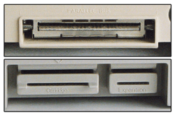
The Parallel Bus Interface, or PBI, is a 50-pin port found on some Atari 8-bit XL computers. It provides unbuffered, direct connection to the system bus lines (address, data, control), running at the same speed as the 6502 CPU. The 600XL and 800XL computers, along with the unreleased 1400XL and 1450XLD had a PBI interface.
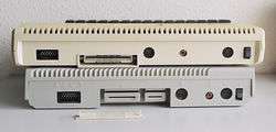
The Enhanced Cartridge Interface, or ECI, was a modified version of the PBI designed to be smaller and less expensive to implement. Many of the pins in the PBI were duplicated in the 30-pin cartridge slot, so ECI was limited to only those 14 pins in the PBI that were not in the cartridge slot. Placed side-by-side on the back of the computer, devices plugged into both at the same time to provide the same electrical interface as the PBI. The ECI was found on the 65XE (European version), the 130XE and the 800XE.
Details
The PBI is implemented as a rectangular 50-pin edge connector on the back of XL machines. The pins include all 16 address lines (A0 through A15) and 8 data lines (D0 through D7). Other pins include various electrical supplies, clock signals, interrupts, memory strobes, and even an analog audio input.
As many of these pins were already implemented as part of the already-existing 30-pin ROM cartridge slots on Atari machines, the XE series re-implemented the PBI to include only those pins that the PBI had but the cartridge slot didn't. The resulting connector contained only 14 pins, mostly the address pins A13 though A15, and the various sound and signal pins of the PBI. The ECI slot was placed beside the cartridge slot, allowing a single connector to be inserted into both connectors and re-create the functionality of the entire PBI.
Pinout
| Parallel Bus Interface (PBI) - looking at the back | ||||||||||||||||||||||||
| 1 | 3 | 5 | 7 | 9 | 11 | 13 | 15 | 17 | 19 | 21 | 23 | 25 | 27 | 29 | 31 | 33 | 35 | 37 | 39 | 41 | 43 | 45 | 47 | 49 |
| 2 | 4 | 6 | 8 | 10 | 12 | 14 | 16 | 18 | 20 | 22 | 24 | 26 | 28 | 30 | 32 | 34 | 36 | 38 | 40 | 42 | 44 | 46 | 48 | 50 |
| Parallel Bus Interface (PBI) - Pinout | ||||||||||||||||||||||||
| Pin | TOP | Pin | BOTTOM | |||||||||||||||||||||
| 1 | GND Ground | 2 | External select | |||||||||||||||||||||
| 3 | A0 Address output | 4 | A1 | |||||||||||||||||||||
| 5 | A2 | 6 | A3 | |||||||||||||||||||||
| 7 | A4 | 8 | A5 | |||||||||||||||||||||
| 9 | A6 | 10 | GND | |||||||||||||||||||||
| 11 | A7 | 12 | A8 | |||||||||||||||||||||
| 13 | A9 | 14 | A10 | |||||||||||||||||||||
| 15 | A11 | 16 | A12 | |||||||||||||||||||||
| 17 | A13 | 18 | A14 | |||||||||||||||||||||
| 19 | GND | 20 | A15 | |||||||||||||||||||||
| 21 | D0 Data (bidirectional) | 22 | D1 | |||||||||||||||||||||
| 23 | D2 | 24 | D3 | |||||||||||||||||||||
| 25 | D4 | 26 | D5 | |||||||||||||||||||||
| 27 | D6 | 28 | D7 | |||||||||||||||||||||
| 29 | GND | 30 | GND | |||||||||||||||||||||
| 31 | Phase 2 clock output | 32 | GND | |||||||||||||||||||||
| 33 | NC Reserved | 34 | Reset output | |||||||||||||||||||||
| 35 | (IRQ) Interrupt request | 36 | Ready input | |||||||||||||||||||||
| 37 | NC | 38 | External decoder output | |||||||||||||||||||||
| 39 | NC | 40 | Refresh output | |||||||||||||||||||||
| 41 | Column address output | 42 | GND | |||||||||||||||||||||
| 43 | MPD Math pack disable input | 44 | Row address strobe | |||||||||||||||||||||
| 45 | GND | 46 | Latch read/write out | |||||||||||||||||||||
| 47 | NC (+5V on 600XL only) | 48 | NC (+5V on 600XL only, used for 1064) | |||||||||||||||||||||
| 49 | Audio input | 50 | GND | |||||||||||||||||||||
Devices
- Atari 1064 Memory Module - Designed specifically for the 600XL, it upgraded the memory of the 600XL to 64kB. Only parallel bus device released by Atari.
- Atari 1090 Expansion System - Designed to give expansion slots to the XL computers. Never released.
- ICD Multi I/O Board - Hooked up to either a PBI or ECI connection. Featured a RAMdisk, parallel port, serial port, print spooler and a hard disk interface.
- Black Box - The Black Box by CSS hooks up to either PBI or ECI connection. Featured a SCSI interface, a serial port, parallel port, floppy drive interface and a built-in menu system.
- SupraDrive - an early SCSI disk drive.
- Karin Maxi, a parallel floppy disk drive.
References
- Ian Chadwick, Appendix 14: The XL/XE Parallel Bus, Mapping the Atari Revised Edition, COMPUTE! Publications, ISBN 0-87455-004-1
External links
- ICD Boosts 8-bit Atari Power Antic Magazine. Review on ICD products for the Atari.