Mechanical fan
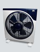
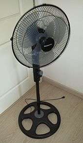
A fan is a machine used to create flow within a fluid, typically a gas such as air.[1] The fan consists of a rotating arrangement of vanes or blades which act on the fluid. The rotating assembly of blades and hub is known as an impeller, a rotor, or a runner. Usually, it is contained within some form of housing or case.[2] This may direct the airflow or increase safety by preventing objects from contacting the fan blades. Most fans are powered by electric motors, but other sources of power may be used, including hydraulic motors and internal combustion engines. Fans produce flows with high volume and low pressure (although higher than ambient pressure), as opposed to compressors which produce high pressures at a comparatively low volume. A fan blade will often rotate when exposed to a fluid stream, and devices that take advantage of this, such as anemometers and wind turbines, often have designs similar to that of a fan.
Typical applications include climate control and personal thermal comfort (e.g., an electric table or floor fan), vehicle and machinery cooling systems, ventilation, fume extraction, winnowing (e.g., separating chaff of cereal grains), removing dust (e.g. in a vacuum cleaner), drying (usually in combination with heat) and to provide draft for a fire. While fans are often used to cool people, they do not actually cool air (if anything, electric fans warm it slightly due to the warming of their motors), but work by evaporative cooling of sweat and increased heat convection into the surrounding air due to the airflow from the fans. Thus, fans may become ineffective at cooling the body if the surrounding air is near body temperature and contains high humidity.
Etymology
The word fan comes from Middle English, winnowing fan, from Old English fann and from Latin vannus.[1]
History
The punkah fan was used in India about 500 BCE. It was a handheld fan made from bamboo strips or other plant fibre, that could be rotated or fanned to move air. During British rule, the word came to be used by Anglo-Indians to mean a large swinging flat fan, fixed to the ceiling, and pulled by a servant, called the punkawallah.
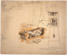
In the 17th century, the experiments of scientists like Otto von Guericke, Robert Hooke and Robert Boyle, established the basic principles of vacuum and airflow. The English architect Sir Christopher Wren applied an early ventilation system in the Houses of Parliament that used bellows to circulate air. Wren's design would be the catalyst for much later improvement and innovation.
John Theophilus Desaguliers, a British engineer, demonstrated a successful use of a fan system to draw out stagnant air from coal mines in 1727 and soon afterwards he installed a similar apparatus in Parliament.[3] Good ventilation was particularly important in coal mines to reduce casualties from asphyxiation. The civil engineer John Smeaton, and later John Buddle installed reciprocating air pumps in the mines in the North of England. However, this arrangement was not ideal as the machinery was liable to breaking down.
Steam
With the advent of practical steam power, fans could finally be used for ventilation. David Boswell Reid, a Scottish physician, installed four steam powered fans in the ceiling of St George's Hospital in Liverpool, so that the pressure produced by the fans would force the incoming air upward and through vents in the ceiling.[4] In 1849 a 6 m radius steam driven fan, designed by William Brunton, was made operational in the Gelly Gaer Colliery of South Wales. The model was exhibited at the Great Exhibition of 1851. Improvements in the technology were made by James Nasmyth, Frenchman Theophile Guibal and J. R. Waddle.[5]
Electrical
Between the years 1882 and 1886, New Orleans, LA resident Schuyler Skaats Wheeler invented a fan powered by electricity.[6] It was commercially marketed by the American firm Crocker & Curtis electric motor company. In 1882, Philip Diehl introduced the electric ceiling fan. During this intense period of innovation, fans powered by alcohol, oil, or kerosene were common around the turn of the 20th century.
In 1909, KDK pioneered the invention of mass-produced electric fans for home use. In the 1920s, industrial advances allowed steel fans to be mass-produced in different shapes, bringing fan prices down and allowing more homeowners to afford them. In the 1930s, the first art deco fan (the "swan fan") was designed. By the 1950s, fans were manufactured in colors that were bright and eye catching.
Window and central air conditioning in the 1960s caused many companies to discontinue production of fans.[7] But in the 1970s, with an increasing awareness of the cost of electricity and the amount of energy used to heat and cool homes, Victorian-style ceiling fans became popular again as both decorative and energy efficient units.
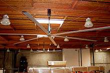
In 1998, Walter K. Boyd invented the HVLS ceiling fan. It was a slow moving fan with an eight foot diameter. Due to its size, the fan moved a large column of air and continuously mixed fresh air with the stale air inside. They are used in many industrial and agricultural settings, because of their energy efficiency.[8]
Types of fans
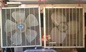

Revolving blade fans are made in a wide range of designs. They are used on the floor, table, desk, or hung from the ceiling. They can also be built into a window, wall, roof, chimney, etc. Most electronic systems such as computers include fans to cool circuits inside, and in appliances such as hair dryers and portable space heaters and mounted/installed wall heaters. They are also used for moving air in air-conditioning systems, and in automotive engines, where they are driven by belts or by direct motor. Fans used for comfort create a wind chill, but do not lower temperatures directly. Fans used to cool electrical equipment or in engines or other machines do cool the equipment directly by forcing hot air into the cooler environment outside the machine. There are three main types of fans used for moving air, axial, centrifugal (also called radial) and cross flow (also called tangential). The American Society of Mechanical Engineers Performance Testing Code 11 (PTC)[9] provides standard procedures for conducting and reporting tests on fans, including those of the centrifugal, axial, and mixed flows.
Axial-flow fans
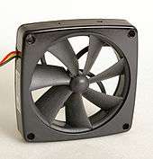
Axial-flow fans have blades that force air to move parallel to the shaft about which the blades rotate. This type of fan is used in a wide variety of applications, ranging from small cooling fans for electronics to the giant fans used in wind tunnels. Axial flow fans are applied in air conditioning and industrial process applications. Standard axial flow fans have diameters from 300–400 mm or 1800 to 2000 mm and work under pressures up to 800 Pa. Examples of axial fans are:
- Table fan: Basic elements of a typical table fan include the fan blade, base, armature and lead wires, motor, blade guard, motor housing, oscillator gearbox, and oscillator shaft. The oscillator is a mechanism that moves the fan from side to side. The axle comes out on both ends of the motor, one end of the axle is attached to the blade and the other is attached to the oscillator gearbox. The motor case joins to the gearbox to contain the rotor and stator. The oscillator shaft combines to the weighted base and the gearbox. A motor housing covers the oscillator mechanism. The blade guard joins to the motor case for safety.
- Ceiling fan: A fan suspended from the ceiling of a room is a ceiling fan. Ceiling fans can be found in both residential and industrial/commercial settings.
- In automobiles, a mechanical fan provides engine cooling and prevents the engine from overheating by blowing or sucking air through a coolant-filled radiator. It can be driven with a belt and pulley off the engine's crankshaft or an electric fan switched on or off by a thermostatic switch.
- Computer cooling fan for cooling electrical components
- variable-pitch fan: A variable-pitch fan is used where precise control of static pressure within supply ducts is required. The blades are arranged to rotate upon a control-pitch hub. The fan wheel will spin at a constant speed. As the hub moves toward the rotor, the blades increase their angle of attack and an increase in flow results.
Centrifugal fan

Often called a "squirrel cage" (because of its similarity in appearance to exercise wheels for pet rodents) or "scroll fan", the centrifugal fan has a moving component (called an impeller) that consists of a central shaft about which a set of blades, or ribs, are positioned. Centrifugal fans blow air at right angles to the intake of the fan, and spin the air outwards to the outlet (by deflection and centrifugal force). The impeller rotates, causing air to enter the fan near the shaft and move perpendicularly from the shaft to the opening in the scroll-shaped fan casing. A centrifugal fan produces more pressure for a given air volume, and is used where this is desirable such as in leaf blowers, blowdryers, air mattress inflators, inflatable structures, climate control, and various industrial purposes. They are typically quieter than comparable axial fans.
Cross-flow fan
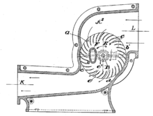
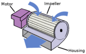
The cross-flow or tangential fan, sometimes known as a tubular fan, was patented in 1893 by Paul Mortier,[10] and is used extensively in the HVAC industry. The fan is usually long in relation to the diameter, so the flow approximately remains two-dimensional away from the ends. The CFF uses an impeller with forward curved blades, placed in a housing consisting of a rear wall and vortex wall. Unlike radial machines, the main flow moves transversely across the impeller, passing the blading twice. The flow within a cross-flow fan may be broken up into three distinct regions: a vortex region near the fan discharge, called an eccentric vortex, the through-flow region, and a paddling region directly opposite. Both the vortex and paddling regions are dissipative, and as a result, only a portion of the impeller imparts usable work on the flow. The cross-flow fan, or transverse fan, is thus a two-stage partial admission machine. The popularity of the crossflow fan in the HVAC industry comes from its compactness, shape, quiet operation, and ability to provide high pressure coefficient. Effectively a rectangular fan in terms of inlet and outlet geometry, the diameter readily scales to fit the available space, and the length is adjustable to meet flow rate requirements for the particular application. Common household tower fans are also cross-flow fans.
Much of the early work focused on developing the cross-flow fan for both high and low-flow-rate conditions, and resulted in numerous patents. Key contributions were made by Coester, Ilberg and Sadeh, Porter and Markland, and Eck.
One phenomenon particular to the cross-flow fan is that, as the blades rotate, the local air incidence angle changes. The result is that in certain positions the blades act as compressors (pressure increase), while at other azimuthal locations the blades act as turbines (pressure decrease).
Uncommon types of fan
Bellows
.svg.png)
Bellows are also used to move air, although not generally considered fans. A hand-operated bellows is essentially a bag with a nozzle and handles, which can be filled with air by one movement, and the air expelled by another. Typically it would comprise two rigid flat surfaces hinged at one end, where a nozzle is fitted, and with handles at the other. The sides of the surfaces are joined by a flexible and air-proof material such as leather; the surfaces and joining material comprise a bag sealed everywhere but at the nozzle. (The joining material typically has a characteristic pleated construction that is so common that similar expanding fabric arrangements not used for moving air, such as on a folding camera, are called bellows.) Separating the handles expands the bag, which fills with air; squeezing them together expels the air. A simple valve (e.g., a flap) may be fitted so that air enters without having to come from the nozzle, which may be close to a fire. Bellows produce a directed pressurized stream of air; the airflow volume is typically low with moderate pressure. They are an older technology, used mainly to produce a strong and directed airflow unlike non-electric bladed mechanical fans, before the introduction of electricity.
- A single-acting bellows will only produce airflow during the exhaust stroke.
- A double-acting bellows is a pair of bellows capable of blowing out air from one while inhaling air into the other, but airflow still temporarily ceases when the stroke direction is reversed.
- Combining multiple bellows at third-cycle or quarter-cycle arrangements on a crank arm allows for nearly continuous airflow from several bellows at once; each is in a different phase of inhaling and exhausting during the cycle.
Coandă effect
The Dyson Air Multiplier fans, and the Imperial C2000 series range hood fans, have no exposed fan blades or other visibly moving parts except their oscillating and tilting head. The airflow is generated using the Coandă effect; a small quantity of air from a high-pressure-bladed impeller fan, contained in the base rather than exposed, drives a large airmass via a low-pressure area created by the airfoil.[11][12][13] The US Patent & Trademark Office initially ruled that Dyson's patent was not an improvement on the Toshiba patent on a nearly identical bladeless desktop fan granted in 1981.[11] Air curtains and air doors also utilize this effect to help retain warm or cool air within an otherwise exposed area that lacks a cover or door. Air curtains are commonly used on open-face dairy, freezer, and vegetable displays to help retain chilled air within the cabinet using a laminar airflow circulated across the display opening, usually generated by a fan in the base of the cabinet.
Convective
Differences in air temperature will affect the density of air and can be used to induce air circulation through the mere act of heating or cooling an air mass. This effect is so subtle and works at such low air pressures that it does not appear to fit the definition of a fan technology. However, prior to the development of electricity, convective airflow was the primary method of inducing airflow in living spaces. Old fashioned oil and coal furnaces were not electric and operated simply on the principle of convection to move the warm air. Very large volume air ducts were sloped upwards away from the top of the furnace towards floor and wall registers above the furnace. Cool air was returned through similar large ducts leading to the bottom of the furnace. Older houses from before electrification often had open duct grilles leading from the ceiling of a lower level to the floor of an upper level, to allow convective airflow to slowly rise up the building from one floor to the next. Outhouses commonly rely on a simple enclosed air channel in a corner of the structure to exhaust offensive odors. Exposed to sunlight, the channel is warmed and a slow convective air current is vented out the top of the building, while fresh air enters the pit through the seat hole.
Electrostatic
An electrostatic fluid accelerator propels airflow by inducing motion in airborne charged particles. A high voltage electric field (commonly 25,000 to 50,000 volts) formed between exposed charged anode and cathode surfaces is capable of inducing airflow through a principle referred to as ionic wind. The airflow pressure is typically very low but the air volume can be large. However, a sufficiently high voltage potential can also cause the formation of ozone and nitrogen oxides, which are reactive and irritating to mucous membranes.
Noise
Fans generate noise from the rapid flow of air around blades and obstacles, and sometimes from the motor. Fan noise has been found to be roughly proportional to the fifth power of fan speed; halving speed reduces noise by about 15 dB.[14]
Fan drive methods

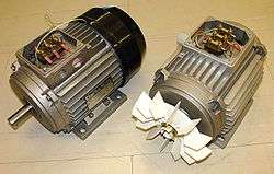
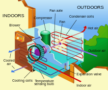
Standalone fans are usually powered by electric motors, often attached directly to the motor's output with no gears or belts. The motor is either hidden in the fan's center hub or extends behind it. For big industrial fans, three-phase asynchronous motors are commonly used, placed near the fan and driving it through a belt and pulleys. Smaller fans are often powered by shaded pole AC motors, or brushed or brushless DC motors. AC-powered fans usually use mains voltage, while DC-powered fans use low voltage, typically 24, 12, or 5 V. Cooling fans for computer equipment always use brushless DC motors, which generate much less electromagnetic interference than other types. In machines with a rotating part, the fan is often connected to it rather than being powered separately. This is commonly seen in motor vehicles with internal combustion engines, where the fan is connected to the drive shaft directly or through a belt and pulleys. A common configuration is a dual-shaft motor, where one end of the shaft drives a mechanism, while the other has a fan mounted on it to cool the motor itself. Window air conditioners commonly use a dual-shaft fan to operate separate blowers for the interior and exterior parts of the device. Where electrical power or rotating parts are not available, fans may be drive by other methods. High-pressure gases such as steam can be used to drive a small turbine, and high-pressure liquids can be used to drive a pelton wheel, which can provide the rotational drive for a fan. Large, slow-moving energy sources such as a flowing river can also power a fan using a water wheel and a train of gears or pulleys.
See also
- Affinity laws
- Axial fan design
- Air cooler
- Balancing machine
- Dyson Air Multiplier
- Fan death
- Industrial fans
- Pump
- Specific fan power
- Waddle fan
- Whole-house fan
References
- 1 2 "Fan". The Free Dictionary By Farlex. Retrieved 2012-05-19.
- ↑ "Fan". Britannica. Retrieved 2012-05-19.
- ↑ "A Short History of Mechanical Fans". The Worshipful Company of Fan Makers. Archived from the original on December 4, 2013.
- ↑ Robert Bruegmann. "Central Heating and Ventilation:Origins and Effects on Architectural Design" (PDF).
- ↑ Cory, William (2010). Fans and Ventilation: A practical guide. Elsevier.
- ↑ "B. A. C. (Before Air Conditioning)" (PDF). New Orleans Bar Association.
- ↑ Fancollectors.org - A Brief History of Fans Information Provided by Steve Cunningham - retrieved July 5, 2010.
- ↑ Information provided by Dianna Huff - retrieved May 18, 2011.
- ↑ ASME PTC 11 - Fans.
- ↑ Paul Mortier. Fan or Blowing apparatus. US Pat. No. 507,445
- 1 2 Wallop, Harry (20 October 2009). "Dyson fan: was it invented 30 years ago?". The Daily Telegraph (London).
- ↑ Dyson Air Multiplier Review: Making a $300 Fan Takes Cojones
- ↑ Video
- ↑ UK Health and Safetey Executive: Top 10 noise control techniques
| Wikimedia Commons has media related to Fans (mechanical). |
| ||||||||||||||||||||||||||||||||||||||||||||||||||
|