Contactor

- In semiconductor testing, contactor can also refer to the specialised socket that connects the device under test.
- In process industries a contactor is a vessel where two streams interact, for example, air and liquid. See Gas-liquid contactor.
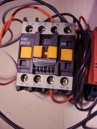
A contactor is an electrically controlled switch used for switching an electrical power circuit, similar to a relay except with higher current ratings.[1] A contactor is controlled by a circuit which has a much lower power level than the switched circuit.
Contactors come in many forms with varying capacities and features. Unlike a circuit breaker, a contactor is not intended to interrupt a short circuit current. Contactors range from those having a breaking current of several amperes to thousands of amperes and 24 V DC to many kilovolts. The physical size of contactors ranges from a device small enough to pick up with one hand, to large devices approximately a meter (yard) on a side.
Contactors are used to control electric motors, lighting, heating, capacitor banks, thermal evaporators, and other electrical loads.
Construction


A contactor has three components. The contacts are the current carrying part of the contactor. This includes power contacts, auxiliary contacts, and contact springs. The electromagnet (or "coil") provides the driving force to close the contacts. The enclosure is a frame housing the contact and the electromagnet. Enclosures are made of insulating materials like Bakelite, Nylon 6, and thermosetting plastics to protect and insulate the contacts and to provide some measure of protection against personnel touching the contacts. Open-frame contactors may have a further enclosure to protect against dust, oil, explosion hazards and weather.
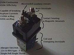
Magnetic blowouts use blowout coils to lengthen and move the electric arc. These are especially useful in DC power circuits. AC arcs have periods of low current, during which the arc can be extinguished with relative ease, but DC arcs have continuous high current, so blowing them out requires the arc to be stretched further than an AC arc of the same current. The magnetic blowouts in the pictured Albright contactor (which is designed for DC currents) more than double the current it can break, increasing it from 600 A to 1,500 A.
Sometimes an economizer circuit is also installed to reduce the power required to keep a contactor closed; an auxiliary contact reduces coil current after the contactor closes. A somewhat greater amount of power is required to initially close a contactor than is required to keep it closed. Such a circuit can save a substantial amount of power and allow the energized coil to stay cooler. Economizer circuits are nearly always applied on direct-current contactor coils and on large alternating current contactor coils.
A basic contactor will have a coil input (which may be driven by either an AC or DC supply depending on the contactor design). The coil may be energized at the same voltage as a motor the contactor is controlling, or may be separately controlled with a lower coil voltage better suited to control by programmable controllers and lower-voltage pilot devices. Certain contactors have series coils connected in the motor circuit; these are used, for example, for automatic acceleration control, where the next stage of resistance is not cut out until the motor current has dropped.[2]
Operating principle
Unlike general-purpose relays, contactors are designed to be directly connected to high-current load devices. Relays tend to be of lower capacity and are usually designed for both normally closed and normally open applications. Devices switching more than 15 amperes or in circuits rated more than a few kilowatts are usually called contactors. Apart from optional auxiliary low current contacts, contactors are almost exclusively fitted with normally open ("form A") contacts. Unlike relays, contactors are designed with features to control and suppress the arc produced when interrupting heavy motor currents.
When current passes through the electromagnet, a magnetic field is produced, which attracts the moving core of the contactor. The electromagnet coil draws more current initially, until its inductance increases when the metal core enters the coil. The moving contact is propelled by the moving core; the force developed by the electromagnet holds the moving and fixed contacts together. When the contactor coil is de-energized, gravity or a spring returns the electromagnet core to its initial position and opens the contacts.
For contactors energized with alternating current, a small part of the core is surrounded with a shading coil, which slightly delays the magnetic flux in the core. The effect is to average out the alternating pull of the magnetic field and so prevent the core from buzzing at twice line frequency.
Because arcing and consequent damage occurs just as the contacts are opening or closing, contactors are designed to open and close very rapidly; there is often an internal tipping point mechanism to ensure rapid action.
Rapid closing can, however, lead to increase contact bounce which causes additional unwanted open-close cycles. One solution is to have bifurcated contacts to minimize contact bounce; two contacts designed to close simultaneously, but bounce at different times so the circuit will not be briefly disconnected and cause an arc.
A slight variant has multiple contacts designed to engage in rapid succession. The first to make contact and last to break will experience the greatest contact wear and will form a high-resistance connection that would cause excessive heating inside the contactor. However, in doing so, it will protect the primary contact from arcing, so a low contact resistance will be established a millisecond later.
Another technique for improving the life of contactors is contact wipe; the contacts move past each other after initial contact in order to wipe off any contamination.
Arc suppression
Without adequate contact protection, the occurrence of electric current arcing causes significant degradation of the contacts, which suffer significant damage. An electrical arc occurs between the two contact points (electrodes) when they transition from a closed to an open (break arc) or from an open to a closed (make arc). The break arc is typically more energetic and thus more destructive.[3]
The heat developed by the resulting electrical arc is very high, ultimately causing the metal on the contact to migrate with the current. The extremely high temperature of the arc (tens of thousands of degrees Celsius) cracks the surrounding gas molecules creating ozone, carbon monoxide, and other compounds. The arc energy slowly destroys the contact metal, causing some material to escape into the air as fine particulate matter. This activity causes the material in the contacts to degrade over time, ultimately resulting in device failure. For example, a properly applied contactor will have a life span of 10,000 to 100,000 operations when run under power; which is significantly less than the mechanical (non-powered) life of the same device which can be in excess of 20 million operations.[4]
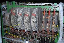
Most motor control contactors at low voltages (600 volts and less) are air break contactors; air at atmospheric pressure surrounds the contacts and extinguishes the arc when interrupting the circuit. Modern medium-voltage AC motor controllers use vacuum contactors. High voltage AC contactors (greater than 1000 volts) may use vacuum or an inert gas around the contacts. High Voltage DC contactors (greater than 600V) still rely on air within specially designed arc-chutes to break the arc energy. High-voltage electric locomotives may be isolated from their overhead supply by roof-mounted circuit breakers actuated by compressed air; the same air supply may be used to "blow out" any arc that forms.[5][6]
Ratings
Contactors are rated by designed load current per contact (pole),[7] maximum fault withstand current, duty cycle, design life expectancy, voltage, and coil voltage. A general purpose motor control contactor may be suitable for heavy starting duty on large motors; so-called "definite purpose" contactors are carefully adapted to such applications as air-conditioning compressor motor starting. North American and European ratings for contactors follow different philosophies, with North American general purpose machine tool contactors generally emphasizing simplicity of application while definite purpose and European rating philosophy emphasizes design for the intended life cycle of the application.
IEC utilization categories
The current rating of the contactor depends on utilization category. Example IEC categories in standard 60947 are described as:
- AC-1 - Non-inductive or slightly inductive loads, resistance furnaces
- AC-2 - Starting of slip-ring motors: starting, switching-off
- AC-3 - Starting of squirrel-cage motors and switching-off only after the motor is up to speed. (Make Locked Rotor Amps (LRA), Break Full Load Amps (FLA))
- AC-4 - Starting of squirrel-cage motors with inching and plugging duty. Rapid Start/Stop. (Make and Break LRA)
Relays and auxiliary contact blocks are rated according to IEC 60947-5-1.
- AC-15 - Control of electromagnetic loads (>72 VA)
- DC-13 - Control of electromagnets
NEMA
NEMA contactors for low-voltage motors (less than 1000 volts) are rated according to NEMA size, which gives a maximum continuous current rating and a rating by horsepower for attached induction motors. NEMA standard contactor sizes are designated 00,0,1,2,3,4,5,6,7,8,9.
The horsepower ratings are based on voltage and on typical induction motor characteristics and duty cycle as stated in NEMA standard ICS2. Exceptional duty cycles or specialized motor types may require a different NEMA starter size than the nominal rating. Manufacturer's literature is used to guide selection for non-motor loads, for example, incandescent lighting or power factor correction capacitors. Contactors for medium-voltage motors (greater than 1000 volts) are rated by voltage and current capacity.
Auxiliary contacts of contactors are used in control circuits and are rated with NEMA contact ratings for the pilot circuit duty required. Normally these contacts are not used in motor circuits. The nomenclature is a letter followed by a three digit number, the letter designates the current rating of the contacts and the current type (i.e., AC or DC) and the number designates the maximum voltage design values.[8]
Applications
Lighting control
Contactors are often used to provide central control of large lighting installations, such as an office building or retail building. To reduce power consumption in the contactor coils, latching contactors are used, which have two operating coils. One coil, momentarily energized, closes the power circuit contacts, which are then mechanically held closed; the second coil opens the contacts.
Magnetic starter
A magnetic starter is a device designed to provide power to electric motors. It includes a contactor as an essential component, while also providing power-cutoff, under-voltage, and overload protection.
Vacuum contactor
Vacuum contactors utilize vacuum bottle encapsulated contacts to suppress the arc. This arc suppression allows the contacts to be much smaller and use less space than air break contacts at higher currents. As the contacts are encapsulated, vacuum contactors are used fairly extensively in dirty applications, such as mining.
Vacuum contactors are only applicable for use in AC systems. The AC arc generated upon opening of the contacts will self-extinguish at the zero-crossing of the current waveform, with the vacuum preventing a re-strike of the arc across the open contacts. Vacuum contactors are therefore very efficient at disrupting the energy of an electric arc and are used when relatively fast switching is required, as the maximum break time is determined by the periodicity of the AC waveform.
References
| Wikimedia Commons has media related to Contactors. |
- ↑ Terrell Croft and Wilford Summers (ed), American Electricans' Handbook, Eleventh Edition, McGraw Hill, New York (1987) ISBN 0-07-013932-6 page 7-124
- ↑ Croft, page 7-125
- ↑ Ragnar Holm (1958). Electric Contacts Handbook (3rd ed.). Springer-Verlag, Berlin / Göttingen / Heidelberg. pp. 331–342.
- ↑ "Lab Note #105 Contact Life - Unsuppressed vs. Suppressed Arcing". Arc Suppression Technologies. April 2011. Retrieved February 5, 2012.
- ↑ Hammond, Rolt (1968). "Development of electric traction". Modern Methods of Railway Operation. London: Frederick Muller. pp. 71–73. OCLC 467723.
- ↑ Ransome-Wallis, Patrick (1959). "Electric motive power". Illustrated Encyclopedia of World Railway Locomotives. London: Hutchinson. p. 173. ISBN 0-486-41247-4. OCLC 2683266.
- ↑ "All about circuits". All about circuits. Retrieved 2013-09-18.
- ↑ "General Information / Technical Data NEMA / EEMAC Ratings" (PDF). Moeller. p. 4/16. Retrieved September 17, 2013 – via KMParts.com.
|