Wireless power
.jpg)
Wireless power transfer (WPT)[1] or wireless energy transmission is the transmission of electrical power from a power source to a consuming device without using solid wires or conductors.[2][3][4][5] It is a generic term that refers to a number of different power transmission technologies that use time-varying electromagnetic fields.[1][5][6][7] Wireless transmission is useful to power electrical devices in cases where interconnecting wires are inconvenient, hazardous, or are not possible. In wireless power transfer, a transmitter device connected to a power source, such as the mains power line, transmits power by electromagnetic fields across an intervening space to one or more receiver devices, where it is converted back to electric power and utilized.[1]
Wireless power techniques fall into two categories, non-radiative and radiative.[1][6][8][9][10] In near-field or non-radiative techniques, power is transferred over short distances by magnetic fields using inductive coupling between coils of wire or in a few devices by electric fields using capacitive coupling between electrodes.[5][8] Some studies using simulation have found possible to transfer power wirelessly within 2 meters distance with an efficiency of 70% at a frequency of 100 kHz.[11] Applications of this type are electric toothbrush chargers, RFID tags, smartcards, and chargers for implantable medical devices like artificial cardiac pacemakers, and inductive powering or charging of electric vehicles like trains or buses.[9][12] A current focus is to develop wireless systems to charge mobile and handheld computing devices such as cellphones, digital music players and portable computers without being tethered to a wall plug. In radiative or far-field techniques, also called power beaming, power is transmitted by beams of electromagnetic radiation, like microwaves or laser beams. These techniques can transport energy longer distances but must be aimed at the receiver. Proposed applications for this type are solar power satellites, and wireless powered drone aircraft.[9] An important issue associated with all wireless power systems is limiting the exposure of people and other living things to potentially injurious electromagnetic fields (see Electromagnetic radiation and health).[9]
Overview

"Wireless power transmission" is a collective term that refers to a number of different technologies for transmitting power by means of time-varying electromagnetic fields.[1][5][8] The technologies, listed in the table below, differ in the distance over which they can transmit power efficiently, whether the transmitter must be aimed (directed) at the receiver, and in the type of electromagnetic energy they use: time varying electric fields, magnetic fields, radio waves, microwaves, or infrared or visible light waves.[8]
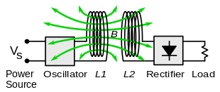
In general a wireless power system consists of a "transmitter" device connected to a source of power such as mains power lines, which converts the power to a time-varying electromagnetic field, and one or more "receiver" devices which receive the power and convert it back to DC or AC electric power which is consumed by an electrical load.[1][8] In the transmitter the input power is converted to an oscillating electromagnetic field by some type of "antenna" device. The word "antenna" is used loosely here; it may be a coil of wire which generates a magnetic field, a metal plate which generates an electric field, an antenna which radiates radio waves, or a laser which generates light. A similar antenna or coupling device in the receiver converts the oscillating fields to an electric current. An important parameter which determines the type of waves is the frequency f in hertz of the oscillations. The frequency determines the wavelength λ = c/f of the waves which carry the energy across the gap, where c is the velocity of light.
Wireless power uses the same fields and waves as wireless communication devices like radio,[6][13] another familiar technology which involves power transmitted without wires by electromagnetic fields, used in cellphones, radio and television broadcasting, and WiFi. In radio communication the goal is the transmission of information, so the amount of power reaching the receiver is unimportant as long as it is enough that the signal to noise ratio is high enough that the information can be received intelligibly.[5][6][13] In wireless communication technologies generally only tiny amounts of power reach the receiver. By contrast, in wireless power, the amount of power received is the important thing, so the efficiency (fraction of transmitted power that is received) is the more significant parameter.[5] For this reason wireless power technologies are more limited by distance than wireless communication technologies.
These are the different wireless power technologies:[1][8][9][14][15]
| Technology | Range[16] | Directivity[8] | Frequency | Antenna devices | Current and or possible future applications |
|---|---|---|---|---|---|
| Inductive coupling | Short | Low | Hz - MHz | Wire coils | Electric tooth brush and razor battery charging, induction stovetops and industrial heaters. |
| Resonant inductive coupling | Mid- | Low | MHz - GHz | Tuned wire coils, lumped element resonators | Charging portable devices (Qi, WiTricity), biomedical implants, electric vehicles, powering busses, trains, MAGLEV, RFID, smartcards. |
| Capacitive coupling | Short | Low | kHz - MHz | Electrodes | Charging portable devices, power routing in large scale integrated circuits, Smartcards. |
| Magnetodynamic[14] | Short | N.A. | Hz | Rotating magnets | Charging electric vehicles. |
| Microwaves | Long | High | GHz | Parabolic dishes, phased arrays, rectennas | Solar power satellite, powering drone aircraft. |
| Light waves | Long | High | ≥THz | Lasers, photocells, lenses | Powering drone aircraft, powering space elevator climbers. |
Field regions
Electric and magnetic fields are created by charged particles in matter such as electrons. A stationary charge creates an electrostatic field in the space around it. A steady current of charges (direct current, DC) creates a static magnetic field around it. The above fields contain energy, but cannot carry power because they are static. However time-varying fields can carry power.[17] Accelerating electric charges, such as are found in an alternating current (AC) of electrons in a wire, create time-varying electric and magnetic fields in the space around them. These fields can exert oscillating forces on the electrons in a receiving "antenna", causing them to move back and forth. These represent alternating current which can be used to power a load.
The oscillating electric and magnetic fields surrounding moving electric charges in an antenna device can be divided into two regions, depending on distance Drange from the antenna.[1][4][6][8][9][10][18] The boundary between the regions is somewhat vaguely defined.[8] The fields have different characteristics in these regions, and different technologies are used for transmitting power:
- Near-field or nonradiative region - This means the area within about 1 wavelength (λ) of the antenna.[1][4][10] In this region the oscillating electric and magnetic fields are separate[6] and power can be transferred via electric fields by capacitive coupling (electrostatic induction) between metal electrodes, or via magnetic fields by inductive coupling (electromagnetic induction) between coils of wire.[5][6][8][9] These fields are not radiative,[10] meaning the energy stays within a short distance of the transmitter.[19] If there is no receiving device or absorbing material within their limited range to "couple" to, no power leaves the transmitter.[19] The range of these fields is short, and depends on the size and shape of the "antenna" devices, which are usually coils of wire. The fields, and thus the power transmitted, decrease exponentially with distance,[4][18][20] so if the distance between the two "antennas" Drange is much larger than the diameter of the "antennas" Dant very little power will be received. Therefore these techniques cannot be used for long distance power transmission.
- Resonance, such as resonant inductive coupling, can increase the coupling between the antennas greatly, allowing efficient transmission at somewhat greater distances,[1][4][6][9][21][22] although the fields still decrease exponentially. Therefore the range of near-field devices is conventionally devided into two categories:
- Short range - up to about one antenna diameter: Drange ≤ Dant.[19][21][23] This is the range over which ordinary nonresonant capacitive or inductive coupling can transfer practical amounts of power.
- Mid-range - up to 10 times the antenna diameter: Drange ≤ 10 Dant.[21][22][23][24] This is the range over which resonant capacitive or inductive coupling can transfer practical amounts of power.
- Far-field or radiative region - Beyond about 1 wavelength (λ) of the antenna, the electric and magnetic fields are perpendicular to each other and propagate as an electromagnetic wave; examples are radio waves, microwaves, or light waves.[1][4][9] This part of the energy is radiative,[10] meaning it leaves the antenna whether or not there is a receiver to absorb it. The portion of energy which does not strike the receiving antenna is dissipated and lost to the system. The amount of power emitted as electromagnetic waves by an antenna depends on the ratio of the antenna's size Dant to the wavelength of the waves λ,[25] which is determined by the frequency: λ = c/f. At low frequencies f where the antenna is much smaller than the size of the waves, Dant << λ, very little power is radiated. Therefore the near-field devices above, which use lower frequencies, radiate almost none of their energy as electromagnetic radiation. Antennas about the same size as the wavelength Dant ≈ λ such as monopole or dipole antennas, radiate power efficiently, but the electromagnetic waves are radiated in all directions (omnidirectionally), so if the receiving antenna is far away, only a small amount of the radiation will hit it.[10][21] Therefore these can be used for short range, inefficient power transmission but not for long range transmission.[26]
- However, unlike fields, electromagnetic radiation can be focused by reflection or refraction into beams. By using a high-gain antenna or optical system which concentrates the radiation into a narrow beam aimed at the receiver, it can be used for long range power transmission.[21][26] From the Rayleigh criterion, to produce the narrow beams necessary to focus a significant amount of the energy on a distant receiver, an antenna must be much larger than the wavelength of the waves used: Dant >> λ = c/f.[27][28] Practical beam power devices require wavelengths in the centimeter region or below, corresponding to frequencies above 1 GHz, in the microwave range or above.[1]
Near-field or non-radiative techniques
The near-field components of electric and magnetic fields die out quickly beyond a distance of about one diameter of the antenna (Dant). Outside very close ranges the field strength and coupling is roughly proportional to (Drange/Dant)−3[18][29] Since power is proportional to the square of the field strength, the power transferred decreases with the sixth power of the distance (Drange/Dant)−6.[6][20][30][31] or 60 dB per decade. In other words, doubling the distance between transmitter and receiver causes the power received to decrease by a factor of 26 = 64.
Inductive coupling
The electrodynamic induction wireless transmission technique relies on the use of a magnetic field generated by an electric current to induce a current in a second conductor. This effect occurs in the electromagnetic near field, with the secondary in close proximity to the primary. As the distance from the primary is increased, more and more of the primary's magnetic field misses the secondary. Even over a relatively short range the inductive coupling is grossly inefficient, wasting much of the transmitted energy.[32]
This action of an electrical transformer is the simplest form of wireless power transmission. The primary coil and secondary coil of a transformer are not directly connected; each coil is part of a separate circuit. Energy transfer takes place through a process known as mutual induction. Principal functions are stepping the primary voltage either up or down and electrical isolation. Mobile phone and electric toothbrush battery chargers, are examples of how this principle is used. Induction cookers use this method. The main drawback to this basic form of wireless transmission is short range. The receiver must be directly adjacent to the transmitter or induction unit in order to efficiently couple with it.
Common uses of resonance-enhanced electrodynamic induction[33] are charging the batteries of portable devices such as laptop computers and cell phones, medical implants and electric vehicles.[34][35][36] A localized charging technique[37] selects the appropriate transmitting coil in a multilayer winding array structure.[38] Resonance is used in both the wireless charging pad (the transmitter circuit) and the receiver module (embedded in the load) to maximize energy transfer efficiency. Battery-powered devices fitted with a special receiver module can then be charged simply by placing them on a wireless charging pad. It has been adopted as part of the Qi wireless charging standard.
This technology is also used for powering devices with very low energy requirements, such as RFID patches and contactless smartcards. Instead of relying on each of the many thousands or millions of RFID patches or smartcards to contain a working battery, electrodynamic induction can provide power only when the devices are needed.
Capacitive coupling
In capacitive coupling (electrostatic induction), the dual of inductive coupling, power is transmitted by electric fields[5] between electrodes such as metal plates. The transmitter and receiver electrodes form a capacitor, with the intervening space as the dielectric.[5][6][9][39][40] An alternating voltage generated by the transmitter is applied to the transmitting plate, and the oscillating electric field induces an alternating potential on the receiver plate by electrostatic induction,[5] which causes an alternating current to flow in the load circuit. The amount of power transferred increases with the frequency[39] and the capacitance between the plates, which is proportional to the area of the smaller plate and (for short distances) inversely proportional to the separation.[5]
Capacitive coupling has only been used practically in a few low power applications, because the very high voltages on the electrodes required to transmit significant power can be hazardous,[6][9] and can cause unpleasant side effects such as noxious ozone production. In addition, in contrast to magnetic fields,[21] electric fields interact strongly with most materials, including the human body, due to dielectric polarization.[40] Intervening materials between or near the electrodes can absorb the energy, in the case of humans possibly causing excessive electromagnetic field exposure.[6] However capacitive coupling has a few advantages over inductive. The field is largely confined between the capacitor plates, reducing interference, which in inductive coupling requires heavy ferrite "flux confinement" cores.[5][40] Also, alignment requirements between the transmitter and receiver are less critical.[5][6][39] Capacitive coupling has recently been applied to charging battery powered portable devices[41] and is being considered as a means of transferring power between substrate layers in integrated circuits.[42]
Magnetodynamic coupling
In this method, power is transmitted between two rotating armature, one in the transmitter and one in the receiver, which rotate synchronously, coupled together by a magnetic field generated by permanent magnets on the armatures.[14] The transmitter armature is turned either by or as the rotor of an electric motor, and its magnetic field exerts torque on the receiver armature, turning it. The magnetic field acts like a mechanical coupling between the armatures.[14] The receiver armature produces power to drive the load, either by turning a separate electric generator or by using the receiver armature itself as the rotor in a generator.
This device has been proposed as an alternative to inductive power transfer for noncontact charging of electric vehicles.[14] A rotating armature embedded in a garage floor or curb would turn a receiver armature in the underside of the vehicle to charge its batteries.[14] It is claimed that this technique can transfer power over distances of 10 to 15 cm (4 to 6 inches) with high efficiency, over 90%.[14] Also, the low frequency stray magnetic fields produced by the rotating magnets produce less electromagnetic interference to nearby electronic devices than the high frequency magnetic fields produced by inductive coupling systems. A prototype system charging electric vehicles has been in operation at University of British Columbia since 2012. Other researchers, however, claim that the two energy conversions (electrical to mechanical to electrical again) make the system less efficient than electrical systems like inductive coupling.[14]
Far-field or radiative techniques
Far field methods achieve longer ranges, often multiple kilometer ranges, where the distance is much greater than the diameter of the device(s). The main reason for longer ranges with radio wave and optical devices is the fact that electromagnetic radiation in the far-field can be made to match the shape of the receiving area (using high directivity antennas or well-collimated laser beams). The maximum directivity for antennas is physically limited by diffraction.
In general, visible light (from lasers) and microwaves (from purpose-designed antennas) are the forms of electromagnetic radiation best suited to energy transfer.
The dimensions of the components may be dictated by the distance from transmitter to receiver, the wavelength and the Rayleigh criterion or diffraction limit, used in standard radio frequency antenna design, which also applies to lasers. Airy's diffraction limit is also frequently used to determine an approximate spot size at an arbitrary distance from the aperture. Electromagnetic radiation experiences less diffraction at shorter wavelengths (higher frequencies); so, for example, a blue laser is diffracted less than a red one.
The Rayleigh criterion dictates that any radio wave, microwave or laser beam will spread and become weaker and diffuse over distance; the larger the transmitter antenna or laser aperture compared to the wavelength of radiation, the tighter the beam and the less it will spread as a function of distance (and vice versa). Smaller antennae also suffer from excessive losses due to side lobes. However, the concept of laser aperture considerably differs from an antenna. Typically, a laser aperture much larger than the wavelength induces multi-moded radiation and mostly collimators are used before emitted radiation couples into a fiber or into space.
Ultimately, beamwidth is physically determined by diffraction due to the dish size in relation to the wavelength of the electromagnetic radiation used to make the beam.
Microwave power beaming can be more efficient than lasers, and is less prone to atmospheric attenuation caused by dust or water vapor.
Then the power levels are calculated by combining the above parameters together, and adding in the gains and losses due to the antenna characteristics and the transparency and dispersion of the medium through which the radiation passes. That process is known as calculating a link budget.
Microwaves

Power transmission via radio waves can be made more directional, allowing longer distance power beaming, with shorter wavelengths of electromagnetic radiation, typically in the microwave range.[43] A rectenna may be used to convert the microwave energy back into electricity. Rectenna conversion efficiencies exceeding 95% have been realized. Power beaming using microwaves has been proposed for the transmission of energy from orbiting solar power satellites to Earth and the beaming of power to spacecraft leaving orbit has been considered.[44][45]
Power beaming by microwaves has the difficulty that, for most space applications, the required aperture sizes are very large due to diffraction limiting antenna directionality. For example, the 1978 NASA Study of solar power satellites required a 1-km diameter transmitting antenna and a 10 km diameter receiving rectenna for a microwave beam at 2.45 GHz.[46] These sizes can be somewhat decreased by using shorter wavelengths, although short wavelengths may have difficulties with atmospheric absorption and beam blockage by rain or water droplets. Because of the "thinned array curse," it is not possible to make a narrower beam by combining the beams of several smaller satellites.
For earthbound applications, a large-area 10 km diameter receiving array allows large total power levels to be used while operating at the low power density suggested for human electromagnetic exposure safety. A human safe power density of 1 mW/cm2 distributed across a 10 km diameter area corresponds to 750 megawatts total power level. This is the power level found in many modern electric power plants.
Following World War II, which saw the development of high-power microwave emitters known as cavity magnetrons, the idea of using microwaves to transmit power was researched. By 1964, a miniature helicopter propelled by microwave power had been demonstrated.[47]
Japanese researcher Hidetsugu Yagi also investigated wireless energy transmission using a directional array antenna that he designed. In February 1926, Yagi and his colleague Shintaro Uda published their first paper on the tuned high-gain directional array now known as the Yagi antenna. While it did not prove to be particularly useful for power transmission, this beam antenna has been widely adopted throughout the broadcasting and wireless telecommunications industries due to its excellent performance characteristics.[48]
Wireless high power transmission using microwaves is well proven. Experiments in the tens of kilowatts have been performed at Goldstone in California in 1975[49][50][51] and more recently (1997) at Grand Bassin on Reunion Island.[52] These methods achieve distances on the order of a kilometer.
Under experimental conditions, microwave conversion efficiency was measured to be around 54%.[53]
More recently, a change to 24 GHz has been suggested as microwave emitters similar to LEDs have been made with very high quantum efficiencies using negative resistance, i.e. Gunn or IMPATT diodes, and this would be viable for short range links.
Lasers

In the case of electromagnetic radiation closer to the visible region of the spectrum (tens of micrometers to tens of nanometres), power can be transmitted by converting electricity into a laser beam that is then pointed at a photovoltaic cell.[54] This mechanism is generally known as "power beaming" because the power is beamed at a receiver that can convert it to electrical energy.
Compared to other wireless methods:[55]
- Collimated monochromatic wavefront propagation allows narrow beam cross-section area for transmission over large distances.
- Compact size: solid state lasers fit into small products.
- No radio-frequency interference to existing radio communication such as Wi-Fi and cell phones.
- Access control: only receivers hit by the laser receive power.
Drawbacks include:
- Laser radiation is hazardous. Low power levels can blind humans and other animals. High power levels can kill through localized spot heating.
- Conversion between electricity and light is inefficient. Photovoltaic cells achieve only 40%–50% efficiency.[56] (Efficiency is higher with monochromatic light than with solar panels).
- Atmospheric absorption, and absorption and scattering by clouds, fog, rain, etc., causes up to 100% losses.
- Requires a direct line of sight with the target.
Laser "powerbeaming" technology has been mostly explored in military weapons[57][58][59] and aerospace[60][61] applications and is now being developed for commercial and consumer electronics. Wireless energy transfer systems using lasers for consumer space have to satisfy laser safety requirements standardized under IEC 60825.
Other details include propagation,[62] and the coherence and the range limitation problem.[63]
Geoffrey Landis[64][65][66] is one of the pioneers of solar power satellites[67] and laser-based transfer of energy especially for space and lunar missions. The demand for safe and frequent space missions has resulted in proposals for a laser-powered space elevator.[68][69]
NASA's Dryden Flight Research Center demonstrated a lightweight unmanned model plane powered by a laser beam.[70] This proof-of-concept demonstrates the feasibility of periodic recharging using the laser beam system.
Energy harvesting
In the context of wireless power, energy harvesting, also called power harvesting or energy scavenging, is the conversion of ambient energy from the environment to electric power, mainly to power small autonomous wireless electronic devices.[71] The ambient energy may come from stray electric or magnetic fields or radio waves from nearby electrical equipment, light, thermal energy (heat), or kinetic energy such as vibration or motion of the device.[71] Although the efficiency of conversion is usually low and the power gathered often minuscule (milliwatts or microwatts),[71] it can be adequate to run or recharge small micropower wireless devices such as remote sensors, which are proliferating in many fields.[71] This new technology is being developed to eliminate the need for battery replacement or charging of such wireless devices, allowing them to operate completely autonomously.
History
In 1826 André-Marie Ampère developed Ampère's circuital law showing that electric current produces a magnetic field.[72] Michael Faraday developed Faraday's law of induction in 1831, describing the electromagnetic force induced in a conductor by a time-varying magnetic flux. In 1862 James Clerk Maxwell synthesized these and other observations, experiments and equations of electricity, magnetism and optics into a consistent theory, deriving Maxwell's equations. This set of partial differential equations forms the basis for modern electromagnetics, including the wireless transmission of electrical energy.[15][73] Maxwell predicted the existence of electromagnetic waves in his 1873 A Treatise on Electricity and Magnetism.[74] In 1884 John Henry Poynting developed equations for the flow of power in an electromagnetic field, Poynting's theorem and the Poynting vector, which are used in the analysis of wireless energy transfer systems.[15][73] In 1888 Heinrich Rudolf Hertz discovered radio waves, confirming the prediction of electromagnetic waves by Maxwell.[74]
Tesla's experiments

Inventor Nikola Tesla performed the first experiments in wireless power transmission at the turn of the 20th century,[73][75] and may have done more to popularize the idea than any other individual. In the period 1891 to 1904 he experimented with transmitting power by inductive and capacitive coupling using spark-excited radio frequency resonant transformers, now called Tesla coils, which generated high AC voltages.[73][75][76] With these he was able to transmit power for short distances without wires. In demonstrations before the American Institute of Electrical Engineers[76] and at the 1893 Columbian Exposition in Chicago he lit light bulbs from across a stage.[75] He found he could increase the distance by using a receiving LC circuit tuned to resonance with the transmitter's LC circuit.[77] using resonant inductive coupling. At his Colorado Springs laboratory during 1899-1900, by using voltages of the order of 20 megavolts generated by an enormous coil, he was able to light three incandescent lamps at a distance of about one hundred feet.[78][79] The resonant inductive coupling which Tesla pioneered is now a familiar technology used throughout electronics; its use in wireless power has been recently rediscovered and it is currently being widely applied to short-range wireless power systems.[75][80]
The inductive and capacitive coupling used in Tesla's experiments is a "near-field" effect,[75] so it is not able to transmit power long distances. However, Tesla was obsessed with developing a wireless power distribution system that could transmit power directly into homes and factories, as proposed in a visionary 1900 article in Century magazine.[81][82][83][84] and believed that resonance was the key. He claimed to be able to transmit power on a worldwide scale, using a method that involved conduction through the Earth and atmosphere.[82][83][84][85] Tesla was vague about his methods. One of his ideas was to use balloons to suspend transmitting and receiving terminals in the air above 30,000 feet (9,100 m) in altitude, where the pressure is lower.[85] At this altitude, Tesla claimed, an ionized layer would allow electricity to be sent at high voltages (millions of volts) over long distances.

In 1901, Tesla began construction of a large high-voltage coil facility, the Wardenclyffe Tower at Shoreham, New York, intended as a prototype transmitter for a "World Wireless System" that was to transmit power worldwide, but by 1904 his investors had pulled out, and the facility was never completed.[83][86] Although Tesla claimed his ideas were proven, he had a history of failing to confirm his ideas by experiment,[87][88] and there seems to be no evidence that he ever transmitted significant power beyond the short-range demonstrations above.[15][73][77][78][88][89][90][91][92] The only report of long-distance transmission by Tesla is a claim, not found in reliable sources, that in 1899 he wirelessly lit 200 light bulbs at a distance of 26 miles (42 km).[78][89] There is no independent confirmation of this putative demonstration;[78][89][93] Tesla did not mention it,[89] and it does not appear in his meticulous laboratory notes.[93][94] It originated in 1944 from Tesla's first biographer, John J. O'Neill,[78] who said he pieced it together from "fragmentary material... in a number of publications".[95] In the 110 years since Tesla's experiments, efforts using similar equipment have failed to achieve long distance power transmission,[75][78][89][91] and the scientific consensus is his World Wireless system would not have worked.[15][73][77][83][89][96][97][98][99] Tesla's world power transmission scheme remains today what it was in Tesla's time, a fascinating dream.[15][83]
Microwaves
Before World War 2, little progress was made in wireless power transmission.[90] Radio was developed for communication uses, but couldn't be used for power transmission due to the fact that the relatively low-frequency radio waves spread out in all directions and little energy reached the receiver.[15][73][90] In radio communication, at the receiver, an amplifier intensifies a weak signal using energy from another source. For power transmission, efficient transmission required transmitters that could generate higher-frequency microwaves, which can be focused in narrow beams towards a receiver.[15][73][90][97]
The development of microwave technology during World War 2, such as the klystron and magnetron tubes and parabolic antennas[90] made radiative (far-field) methods practical for the first time, and the first long-distance wireless power transmission was achieved in the 1960s by William C. Brown.[15][73] In 1964 Brown invented the rectenna which could efficiently convert microwaves to DC power, and in 1964 demonstrated it with the first wireless-powered aircraft, a model helicopter powered by microwaves beamed from the ground.[15][90] A major motivation for microwave research in the 1970s and 80s was to develop a solar power satellite.[73][90] Conceived in 1968 by Peter Glaser, this would harvest energy from sunlight using solar cells and beam it down to Earth as microwaves to huge rectennas, which would convert it to electrical energy on the electric power grid.[15][100] In landmark 1975 high power experiments, Brown demonstrated short range transmission of 475 W of microwaves at 54% DC to DC efficiency, and he and Robert Dickinson at NASA's Jet Propulsion Laboratory transmitted 30 kW DC output power across 1.5 km with 2.38 GHz microwaves from a 26 m dish to a 7.3 x 3.5 m rectenna array.[15][101] The incident-RF to DC conversion efficiency of the rectenna was 80%.[15][101] In 1983 Japan launched MINIX (Microwave Ionosphere Nonlinear Interation Experiment), a rocket experiment to test transmission of high power microwaves through the ionosphere.[15]
In recent years a focus of research has been the development of wireless-powered drone aircraft, which began in 1959 with the Dept. of Defense's RAMP (Raytheon Airborne Microwave Platform) project[90] which sponsored Brown's research. In 1987 Canada's Communications Research Center developed a small prototype airplane called Stationary High Altitude Relay Platform (SHARP) to relay telecommunication data between points on earth similar to a communication satellite. Powered by a rectenna, it could fly at 13 miles (21 km) altitude and stay aloft for months. In 1992 a team at Kyoto University built a more advanced craft called MILAX (MIcrowave Lifted Airplane eXperiment). In 2003 NASA flew the first laser powered aircraft. The small model plane's motor was powered by electricity generated by photocells from a beam of infrared light from a ground based laser, while a control system kept the laser pointed at the plane.
Near-field technologies
Inductive power transfer between nearby coils of wire is an old technology, existing since the transformer was developed in the 1800s. Induction heating has been used for 100 years. With the advent of cordless appliances, inductive charging stands were developed for appliances used in wet environments like electric toothbrushes and electric razors to reduce the hazard of electric shock.
One field to which inductive transfer has been applied is to power electric vehicles. In 1892 Maurice Hutin and Maurice Leblanc patented a wireless method of powering railroad trains using resonant coils inductively coupled to a track wire at 3 kHz.[102] The first passive RFID (Radio Frequency Identification) technologies were invented by Mario Cardullo[103] (1973) and Koelle et al.[104] (1975) and by the 1990s were being used in proximity cards and contactless smartcards.
The proliferation of portable wireless communication devices such as cellphones, tablet, and laptop computers in recent decades is currently driving the development of wireless powering and charging technology to eliminate the need for these devices to be tethered to wall plugs during charging.[105] The Wireless Power Consortium was established in 2008 to develop interoperable standards across manufacturers.[105] Its Qi inductive power standard published in August 2009 enables charging and powering of portable devices of up to 5 watts over distances of 4 cm (1.6 inches).[106] The wireless device is placed on a flat charger plate (which could be embedded in table tops at cafes, for example) and power is transferred from a flat coil in the charger to a similar one in the device.
In 2007, a team led by Marin Soljačić at MIT used coupled tuned circuits made of a 25 cm resonant coil at 10 MHz to transfer 60 W of power over a distance of 2 meters (6.6 ft) (8 times the coil diameter) at around 40% efficiency.[75][107] This technology is being commercialized as WiTricity.
See also
- Beam-powered propulsion
- Beam Power Challenge – one of the NASA Centennial Challenges
- Distributed generation
- Electricity distribution
- Electric power transmission
- Electromagnetic compatibility
- Electromagnetic radiation and health
- Energy harvesting
- Friis transmission equation
- Microwave power transmission
- Resonant inductive coupling
- Thinned array curse
- Wardenclyffe Tower
- World Wireless System
Further reading
- Books and Articles
- Agbinya, Johnson I., Ed. (2012). Wireless Power Transfer. River Publishers. ISBN 8792329233. Comprehensive, theoretical engineering text
- Shinohara, Naoki (2014). Wireless Power Transfer via Radiowaves. John Wiley & Sons. ISBN 1118862961. Engineering text
- Tomar, Anuradha; Gupta, Sunil (July 2012). "Wireless power Transmission: Applications and Components". International Journal of Engineering Research & Technology (ESRSA Publications Pvt. Ltd.) 1 (5): 1–8. ISSN 2278-0181. Brief survey of state of wireless power and applications
- Kurs, André; Karalis, Aristeidis; Moffatt, Robert (July 2007). "Wireless Power Transfer via Strongly Coupled Magnetic Resonances" (PDF). Science (American Association for the Advancement of Science) 317: 83–85. doi:10.1126/science.1143254. ISSN 1095-9203. PMID 17556549. Landmark paper on MIT team's 2007 development of mid-range resonant wireless transmission
- Thibault, G. (2014). Wireless Pasts and Wired Futures. In J. Hadlaw, A. Herman, & T. Swiss (Eds.), Theories of the Mobile Internet. Materialities and Imaginaries. (pp. 126–154). London: Routledge. A short cultural history of wireless power
- Patents
- U.S. Patent 4,955,562, Microwave powered aircraft, John E. Martin, et al. (1990).
- U.S. Patent 3,933,323, Solid state solar to microwave energy converter system and apparatus, Kenneth W. Dudley, et al. (1976).
- U.S. Patent 3,535,543, Microwave power receiving antenna, Carroll C. Dailey (1970).
References
- ↑ 1.0 1.1 1.2 1.3 1.4 1.5 1.6 1.7 1.8 1.9 1.10 1.11 Shinohara, Naoki (2014). Wireless Power Transfer via Radiowaves. John Wiley & Sons. pp. ix–xiii. ISBN 1118862961.
- ↑ Bush, Stephen F. (2014). Smart Grid: Communication-Enabled Intelligence for the Electric Power Grid. John Wiley & Sons. p. 118. ISBN 1118820231.
- ↑ "Wireless energy transfer". Encyclopedia of terms. PC Magazine Ziff-Davis. 2014. Retrieved December 15, 2014.
- ↑ 4.0 4.1 4.2 4.3 4.4 4.5 Rajakaruna, Sumedha; Shahnia, Farhad; Ghosh, Arindam (2014). Plug In Electric Vehicles in Smart Grids: Integration Techniques. Springer. pp. 34–36. ISBN 981287299X.
- ↑ 5.0 5.1 5.2 5.3 5.4 5.5 5.6 5.7 5.8 5.9 5.10 5.11 5.12 Gopinath, Ashwin (August 2013). "All About Transferring Power Wirelessly" (PDF). Electronics For You E-zine (EFY Enterprises Pvt. Ltd.): 52–56. Retrieved January 16, 2015.
- ↑ 6.0 6.1 6.2 6.3 6.4 6.5 6.6 6.7 6.8 6.9 6.10 6.11 6.12 Sazonov, Edward; Neuman, Michael R (2014). Wearable Sensors: Fundamentals, Implementation and Applications. Elsevier. pp. 253–255. ISBN 0124186661.
- ↑ Wilson, Tracy V. (2014). "How Wireless Power Works". How Stuff Works website. InfoSpace LLC. Retrieved December 15, 2014.
- ↑ 8.0 8.1 8.2 8.3 8.4 8.5 8.6 8.7 8.8 8.9 Sun, Tianjia; Xie, Xiang; Zhihua, Wang (2013). Wireless Power Transfer for Medical Microsystems. Springer Science & Business Media. pp. 5–6. ISBN 1461477026.
- ↑ 9.0 9.1 9.2 9.3 9.4 9.5 9.6 9.7 9.8 9.9 9.10 Valtchev, Stanimir S.; Baikova, Elena N.; Jorge, Luis R. (December 2012). "Electromagnetic Field as the Wireless Transporter of Energy" (PDF). Facta Universitatis Ser. Electrical Engineering (Serbia: University of Niš) 25 (3): 171–181. doi:10.2298/FUEE1203171V. Retrieved December 15, 2014.
- ↑ 10.0 10.1 10.2 10.3 10.4 10.5 Agbinya, Johnson I. (2012). Wireless Power Transfer. River Publishers. pp. 1–2. ISBN 8792329233.
- ↑ Beams, D.M.; Nagoorkar, V. (August 2013). "Design and simulation of networks for midrange wireless power transfer". pp. 509–512. doi:10.1109/MWSCAS.2013.6674697. Retrieved 2015-04-25.
- ↑ New Scientist:Wireless charging for electric vehicles hits the road
- ↑ 13.0 13.1 Shinohara 2014 Wireless Power Transfer via Radiowaves, p. 27
- ↑ 14.0 14.1 14.2 14.3 14.4 14.5 14.6 14.7 Ashley, Steven (November 20, 2012). "Wireless recharging: Pulling the plug on electric cars". BBC website. British Broadcasting Corp. Retrieved December 10, 2014.
- ↑ 15.0 15.1 15.2 15.3 15.4 15.5 15.6 15.7 15.8 15.9 15.10 15.11 15.12 15.13 Tomar, Anuradha; Gupta, Sunil (July 2012). "Wireless power Transmission: Applications and Components". International Journal of Engineering Research & Technology 1 (5). ISSN 2278-0181. Retrieved November 9, 2014.
- ↑ "short", "midrange", and "long range" are defined below
- ↑ Coleman, Christopher (2004). An Introduction to Radio Frequency Engineerin. Cambridge University Press. pp. 1–3. ISBN 1139452304.
- ↑ 18.0 18.1 18.2 Agbinya (2012) Wireless Power Transfer, p. 126-129
- ↑ 19.0 19.1 19.2 Umenei, A. E. (June 2011). "Understanding Low Frequency Non-radiative Power Transfer" (PDF). Fulton Innovation, Inc. Retrieved January 3, 2015.
- ↑ 20.0 20.1 Schantz, Hans G. (June 2007). A Real-Time Location System Using Near-Field Electromagnetic Ranging (PDF). 2007 IEEE Antennas and Propagation Society International Symposium, Honolulu, Hawaii, USA. Inst. of Electrical and Electronic Engineers. pp. 3792–3795. Retrieved January 2, 2015.
- ↑ 21.0 21.1 21.2 21.3 21.4 21.5 Karalis, Aristeidis; Joannopoulos, J.D.; Soljačić, Marin (January 2008). "Efficient wireless non-radiative mid-range energy transfer" (PDF). Annals of Physics 323 (1): 34–48. doi:10.1016/j.aop.2007.04.017. Retrieved January 3, 2015.
- ↑ 22.0 22.1 Wong, Elvin (2013). "Seminar: A Review on Technologies for Wireless Electricity" (PDF). HKPC. The Hong Kong Electronic Industries Association Ltd. Retrieved January 3, 2015.
- ↑ 23.0 23.1 "Typically, an inductive coupled system can transmit roughly the diameter of the transmitter."(p. 4) "...mid-range is defined as somewhere between one and ten times the diameter of the transmitting coil."(p. 2) Baarman, David W.; Schwannecke, Joshua (December 2009). "White paper: Understanding Wireless Power" (PDF). Fulton Innovation. Retrieved January 3, 2015.
- ↑ "...strongly coupled magnetic resonance can work over the mid-range distance, defined as several times the resonator size." Agbinya (2012) Wireless Power Transfer, p. 40
- ↑ Smith, Glenn S. (1997). An Introduction to Classical Electromagnetic Radiation. Cambridge University Press. p. 474. ISBN 0521586984.
- ↑ 26.0 26.1 Tan, Yen Kheng (2013). Energy Harvesting Autonomous Sensor Systems: Design, Analysis, and Practical Implementation. CRC Press. pp. 181–182. ISBN 1439892733.
- ↑ Feynman, Richard Phillips; Leighton, Robert B.; Sands, Matthew (1963). The Feynman Lectures on Physics Vol. 1: Mainly Mechanics, Radiation, and Heat. California Institute of Technology. pp. 30.6–30.7. ISBN 0465024939.
- ↑ Thorat, Ashwini Anil; Katariya, S. S. (2013). "Solar Power Satellite" (PDF). IOSR Journal of Electronics and Communication Engineering (Int'l Org. of Scientific Research) 5. ISSN 2278-2834. Retrieved January 4, 2015.
- ↑ "Lighting Lamp by S-W Radio" (PDF). Short Wave and Television (New York: Popular Book Corp.) 8 (4): 166. August 1937. Retrieved March 18, 2015. on http://www.americanradiohistory.com
- ↑ Agbinya, Johnson I. (February 2013). "Investigation of near field inductive communication system models, channels, and experiments" (PDF). Progress In Electromagnetics Research B (EMW Publishing) 49: 130. doi:10.2528/pierb12120512. Retrieved January 2, 2015.
- ↑ Bolic, Miodrag; Simplot-Ryl, David; Stojmenovic, Ivan (2010). RFID Systems: Research Trends and Challenges. John Wiley & Sons. p. 29. ISBN 0470975660.
- ↑ Baarman, David W.; Schwannecke, Joshua (December 2009). "White paper: Understanding Wireless Power" (PDF). Fulton Innovation. Retrieved January 3, 2015.
- ↑ "A New Resonator for High Efficiency Wireless Power Transfer". Antennas and Propagation Society International Symposium (APSURSI), 2013 IEEE.
- ↑ "Wireless charging, Adaptor die, Mar 5th 2009". The Economist. 7 November 2008. Retrieved 4 June 2009.
- ↑ Buley, Taylor (9 January 2009). "Wireless technologies are starting to power devices, 01.09.09, 06:25 pm EST". Forbes. Retrieved 4 June 2009.
- ↑ "Alternative Energy, From the unsustainable...to the unlimited". EETimes.com. 21 June 2010.
- ↑ Patent Application PCT/CN2008/0728855
- ↑ Patent US7164255
- ↑ 39.0 39.1 39.2 Huschens, Markus (2012). "Various techniques for wireless charging" (PDF). EETimes-Asia (eMedia Asia Ltd). Retrieved January 16, 2015.
- ↑ 40.0 40.1 40.2 Puers, R. (2008). Omnidirectional Inductive Powering for Biomedical Implants. Springer Science & Business Media. pp. 4–5. ISBN 1402090757.
- ↑ "World's first!! Production starts for Capacitive Coupling Wireless Power Transmission Module". ECN magazine (Advantage Business Media). October 27, 2011. Retrieved January 16, 2015.
- ↑ Meindl, James D. (2008). Integrated Interconnect Technologies for 3D Nanoelectronic Systems. Artech House. pp. 475–477. ISBN 1596932473.
- ↑ Massa, A. Massa, G. Oliveri, F. Viani, and P. Rocca; Oliveri, Giacomo; Viani, Federico; Rocca, Paolo (June 2013). "Array designs for long-distance wireless power transmission - State-of-the-art and innovative solutions". Proceedings of the IEEE 101 (6): 1464–1481. doi:10.1109/JPROC.2013.2245491.
- ↑ G. A. Landis, "Applications for Space Power by Laser Transmission," SPIE Optics, Electro-optics & Laser Conference, Los Angeles CA, 24–28 January 1994; Laser Power Beaming, SPIE Proceedings Vol. 2121, 252–255.
- ↑ G. Landis, M. Stavnes, S. Oleson and J. Bozek, "Space Transfer With Ground-Based Laser/Electric Propulsion" (AIAA-92-3213) NASA Technical Memorandum TM-106060 (1992).
- ↑ Landis, Geoffrey A. (7–12 May 2006). Reevaluating Satellite Solar Power Systems for Earth (PDF). IEEE 4th World Conference on Photovoltaic Energy Conversion. p. 2. Retrieved 11 May 2012.
- ↑ Experimental Airborne Microwave Supported Platform Descriptive Note : Final rept. Jun 64 – Apr 65
- ↑ "Scanning the Past: A History of Electrical Engineering from the Past, Hidetsugu Yagi". Ieee.cincinnati.fuse.net. Retrieved 4 June 2009.
- ↑ "Space Solar Energy Initiative". Space Island Group. Retrieved 4 June 2009.
- ↑ Wireless Power Transmission for Solar Power Satellite (SPS) (Second Draft by N. Shinohara), Space Solar Power Workshop, Georgia Institute of Technology
- ↑ Brown., W. C. (September 1984). "The History of Power Transmission by Radio Waves". Microwave Theory and Techniques, IEEE Transactions on 32 (Volume: 32, Issue: 9 On page(s): 1230–1242+ ISSN: 0018–9480): 1230–1242. Bibcode:1984ITMTT..32.1230B. doi:10.1109/TMTT.1984.1132833.
- ↑ POINT-TO-POINT WIRELESS POWER TRANSPORTATION IN REUNION ISLAND 48th International Astronautical Congress, Turin, Italy, 6–10 October 1997 – IAF-97-R.4.08 J. D. Lan Sun Luk, A. Celeste, P. Romanacce, L. Chane Kuang Sang, J. C. Gatina – University of La Réunion – Faculty of Science and Technology.
- ↑ Brown, W.C.; Eves, E.E. (June 1992). "Beamed microwave power transmission and its application to space". IEEE Transactions on Microwave Theory and Techniques 40 (6): 1239–1250. doi:10.1109/22.141357.
- ↑ Sahai., A.; Graham, David (2 June 2011). "Optical wireless power transmission at long wavelengths". IEEE International Conference on Space Optical Systems and Applications (ICSOS), 2011, Santa Monica, CA (Print ISBN 978–1–4244–9686–0): 164–170. doi:10.1109/ICSOS.2011.5783662. ISBN 978-1-4244-9686-0.
- ↑ Smith, David (4 January 2009). "Wireless power spells end for cables". The Observer (London).
- ↑ "power transmission via lasers". Laserfocusworld.com. Retrieved 4 June 2009.
- ↑ Skillings, Jonathan (23 August 2008). "Laser weapons: A distant target, CNET news August 23, 2008 1:41 pm PDT". News.cnet.com. Retrieved 4 June 2009.
- ↑ "Laser Weapons "Almost Ready?" Not!". Defensetech.org. Retrieved 4 June 2009.
- ↑ "White Sands testing new laser weapon system, US Army.mil, 30 Jan 2009". Army.mil. 30 January 2009. Retrieved 4 June 2009.
- ↑ "Lasers Power Planes, Drones". Defensetech.org. Retrieved 4 June 2009.
- ↑ "Riding a Beam of Light". Space.com. 24 October 2005. Retrieved 4 June 2009.
- ↑ "Free-Space Laser Propagation: Atmospheric Effects". Ieee.org. Retrieved 4 June 2009.
Propagation Characteristics of Laser Beams – Melles Griot catalog
L. C. Andrews and R. L. Phillips, Laser Beam Propagation through Random Media, 2nd ed. (SPIE Press, 2005). Google Books. 2005. ISBN 978-0-8194-5948-0. Retrieved 4 June 2009. - ↑ Dr. Rüdiger Paschotta. "An explanation of Coherence". Rp-photonics.com. Retrieved 4 June 2009.
- ↑ "An Evolutionary Path to SPS". Islandone.org. Retrieved 4 June 2009.
- ↑ "A Supersynchronous SPS". Geoffreylandis.com. 28 August 1997. Retrieved 4 June 2009.
- ↑ "Papers Relating to Space Photovoltaic Power, Power beaming, and Solar Power Satellites". Sff.net. doi:10.1089/153110701753198927. Retrieved 4 June 2009.
- ↑ "Limitless clean energy from space". Nss.org. Retrieved 4 June 2009.
- ↑ "Power Beaming (Climber) Competition". Spaceward.org. Retrieved 4 June 2009.
- ↑ "From Concept to Reality". The Space Elevator. Retrieved 4 June 2009.
"Space Elevator Tethers Coming Closer". Crnano.typepad.com. 31 January 2009. Retrieved 4 June 2009. - ↑ "Dryden Flight Research Center, Beamed Laser Power For UAVs". Nasa.gov. 7 May 2008. Retrieved 4 June 2009.
- ↑ 71.0 71.1 71.2 71.3 Beeby, Stephen; White, Neil (2010). Energy Harvesting for Autonomous Systems. Artech House. pp. 1–2. ISBN 159693719X.
- ↑ Richard Fitzpatrick (2007). "Ampère's Circuital Law".
- ↑ 73.0 73.1 73.2 73.3 73.4 73.5 73.6 73.7 73.8 73.9 Shinohara (2014) Wireless Power Transfer via Radiowaves, p. 11
- ↑ 74.0 74.1 Angelo, Joseph A. (2009). Encyclopedia of Space and Astronomy. Infobase Publishing. pp. 292–293. ISBN 1438110189.
- ↑ 75.0 75.1 75.2 75.3 75.4 75.5 75.6 Lee, C.K.; Zhong, W.X.; Hui, S.Y.R. (September 5, 2012). Recent Progress in Mid-Range Wireless Power Transfer (PDF). The 4th Annual IEEE Energy Conversion Congress and Exposition (ECCE 2012). Raleigh, North Carolina: Inst. of Electrical and Electronic Engineers. pp. 3819–3821. Retrieved November 4, 2014.
- ↑ 76.0 76.1 Tesla, Nikola (May 20, 1891) Experiments with Alternate Currents of Very High Frequency and Their Application to Methods of Artificial Illumination, lecture before the American Inst. of Electrical Engineers, Columbia College, New York. Reprinted as a book of the same name by. Wildside Press. 2006. ISBN 0809501627.
- ↑ 77.0 77.1 77.2 Wheeler, L. P. (August 1943). "Tesla's contribution to high frequency". Electrical Engineering (IEEE) 62 (8): 355–357. doi:10.1109/EE.1943.6435874. ISSN 0095-9197.
- ↑ 78.0 78.1 78.2 78.3 78.4 78.5 Cheney, Margaret; Uth, Robert; Glenn, Jim (1999). Tesla, Master of Lightning. Barnes & Noble Publishing. pp. 90–92. ISBN 0760710058.
- ↑ Tesla was notoriously secretive about the distance he could transmit power. One of his few disclosures of details was in Tesla, Nikola (June 1900). "The Problem of Increasing Human Energy". Century Magazine (New York: The Century Co.). Retrieved November 20, 2014. fig. 7. The caption reads: "EXPERIMENT TO ILLUSTRATE AN INDUCTIVE EFFECT OF AN ELECTRICAL OSCILLATOR OF GREAT POWER - The photograph shows three ordinary incandescent lamps lighted to full candle-power by currents induced in a local loop consisting of a single wire forming a square of fifty feet each side, which includes the lamps, and which is at a distance of one hundred feet from the primary circuit energized by the oscillator. The loop likewise includes an electrical condenser, and is exactly attuned to the vibrations of the oscillator, which is worked at less than five percent of its total capacity."
- ↑ Leyh, G. E.; Kennan, M. D. (September 28, 2008). Efficient wireless transmission of power using resonators with coupled electric fields (PDF). NAPS 2008 40th North American Power Symposium, Calgary, September 28–30, 2008. Inst. of Electrical and Electronic Engineers. pp. 1–4. doi:10.1109/NAPS.2008.5307364. ISBN 978-1-4244-4283-6. Retrieved November 20, 2014.
- ↑ Tesla, Nikola (June 1900). "The Problem of Increasing Human Energy". Century Magazine (New York: The Century Co.). Retrieved November 20, 2014.
- ↑ 82.0 82.1 Tesla, Nikola (March 5, 1904). "The Transmission of Electric Energy Without Wires". Electrical World and Engineer (McGraw Publishing Co.) 43: 23760–23761. Retrieved November 19, 2014., reprinted in Scientific American Supplement, Munn and Co., Vol. 57, No. 1483, June 4, 1904, p. 23760-23761
- ↑ 83.0 83.1 83.2 83.3 83.4 Broad, William J. (May 4, 2009). "A Battle to Preserve a Visionary’s Bold Failure". New York Times (New York: The New York Times Co.). pp. D1. Retrieved November 19, 2014.
- ↑ 84.0 84.1 Carlson 2013 Tesla: Inventor of the Electrical Age, p. 209-210
- ↑ 85.0 85.1 US Patent No. 645576, Nikola Tesla, System of transmission of electrical energy, filed September 2, 1897; granted March 20, 1900
- ↑ Carlson 2013 Tesla: Inventor of the Electrical Age, Ch. 14 & 15, p. 302-367
- ↑ Hawkins, Lawrence A. (February 1903). "Nikola Tesla: His Work and Unfulfilled Promises". The Electrical Age 30 (2): 107–108. Retrieved November 4, 2014.
- ↑ 88.0 88.1 Carlson, W. Bernard (2013). Tesla: Inventor of the Electrical Age. Princeton University Press. pp. 294, 301. ISBN 1400846552.
- ↑ 89.0 89.1 89.2 89.3 89.4 89.5 Coe, Lewis (2006). Wireless Radio: A History. McFarland. p. 112. ISBN 0786426624.
- ↑ 90.0 90.1 90.2 90.3 90.4 90.5 90.6 90.7 Brown, William C. (1984). "The history of power transmission by radio waves". MTT-Trans. on Microwave Theory and Technique (Inst. of Electrical and Electronic Engineers) 32 (9): 1230–1234. doi:10.1109/tmtt.1984.1132833. Retrieved November 20, 2014.
- ↑ 91.0 91.1 Dunning, Brian (January 15, 2013). "Did Tesla plan to transmit power world-wide through the sky?". The Cult of Nikola Tesla. Skeptoid.com. Retrieved November 4, 2014.
- ↑ "Life and Legacy: Colorado Springs". Tesla: Master of Lightning - companion site for 2000 PBS television documentary. PBS.org, US Public Broadcasting Service website. 2000. Retrieved November 19, 2014.
- ↑ 93.0 93.1 Dunning, Brian (January 15, 2013). "Did Tesla cause a field of light bulbs 26 miles away to illuminate wirelessly?". The Cult of Nikola Tesla. Skeptoid.com. Retrieved November 4, 2014.
- ↑ Tesla, Nikola; Marinčić, Aleksandar, Ed. (1977). Colorado Springs Notes, 1899-1900. Beograd, Yugoslavia: The Nikola Tesla Museum.
- ↑ O'Neill, John J. (1944). Prodigal Genius: The life of Nikola Tesla. Ives Washburn, Inc. p. 193.
- ↑ Wearing, Judy (2009). Edison's Concrete Piano: Flying Tanks, Six-Nippled Sheep, Walk-On-Water Shoes, and 12 Other Flops From Great Inventors. ECW Press. p. 98. ISBN 1554905516.
- ↑ 97.0 97.1 Curty, Jari-Pascal; Declercq, Michel; Dehollain, Catherine; Joehl, Norbert (2006). Design and Optimization of Passive UHF RFID Systems. Springer. p. 4. ISBN 0387447105.
- ↑ Belohlavek, Peter; Wagner, John W (2008). Innovation: The Lessons of Nikola Tesla. Blue Eagle Group. pp. 78–79. ISBN 9876510096.
- ↑ "Dennis Papadopoulos interview". Tesla: Master of Lightning - companion site for 2000 PBS television documentary. PBS.org, US Public Broadcasting Service website. 2000. Retrieved November 19, 2014.
- ↑ Glaser, Peter E. (November 22, 1968). "Power from the Sun: Its future" (PDF). Science (American Assoc. for the Advancement of Science) 162 (3856): 857–861. doi:10.1126/science.162.3856.857. Retrieved November 4, 2014.
- ↑ 101.0 101.1 Dickinson, Richard M. (1976). "Performance of a high-power 2.388 GHz receiving array in wireless power transmission over 1.54 km." (PDF). MTT-S Int'l Microwave Symposium Digest: 139–141. doi:10.1109/mwsym.1976.1123672. Retrieved November 9, 2014.
- ↑ US Patent No. 527857A, Maurice Hutin, Maurice Leblanc, Transformer system for electric railways, filed November 16, 1892; granted October 23, 1894
- ↑ US Patent No. 3713148A, Mario W. Cardullo, William L. Parks, Transponder apparatus and system, filed May 21, 1970; granted January 23, 1973
- ↑ Koelle, A. R.; Depp, S. W.; Freyman, R. W. (1975). "Short-range radio-telemetry for identifiction, using modulated RF backscatter". Proc. of the IEEE (Inst. of Electrical and Electronic Engineers) 63 (8): 1260–1261. doi:10.1109/proc.1975.9928.
- ↑ 105.0 105.1 Sayer, Peter (Dec 19, 2008). "Wireless Power Consortium to Unleash Electronic Gadgets". PCWorld (IDG Consumer and SMB). Retrieved December 8, 2014.
- ↑ "Global Qi Standard Powers Up Wireless Charging". PRNewswire (UBM plc). September 2, 2009. Retrieved December 8, 2014.
- ↑ Kurs, André; Karalis, Aristeidis; Moffatt, Robert (July 2007). "Wireless Power Transfer via Strongly Coupled Magnetic Resonances" (PDF). Science (American Association for the Advancement of Science) 317: 83–85. doi:10.1126/science.1143254. ISSN 1095-9203. PMID 17556549.
External links
- Howstuffworks "How Wireless Power Works" – describes near-range and mid-range wireless power transmission using induction and radiation techniques.
- Microwave Power Transmission, – its history before 1980.
- The Stationary High Altitude Relay Platform (SHARP), – microwave beam powered.
- Marin Soljačić's MIT WiTricity – wireless power transmission pages.
- Rezence – official site of a wireless power standard promoted by the Alliance for Wireless Power
- Qi – official site of a wireless power standard promoted by the Wireless Power Consortium
- PMA – official site of a wireless power standard promoted by the Power Matters Alliance
- WiPow – official site of the WiPow Coalition, promoting standardized wireless power for medical, mobility and wheeled devices
