Wien bridge oscillator

A Wien bridge oscillator is a type of electronic oscillator that generates sine waves. It can generate a large range of frequencies. The oscillator is based on a bridge circuit originally developed by Max Wien in 1891.[1] The bridge comprises four resistors and two capacitors. The oscillator can also be viewed as a positive gain amplifier combined with a bandpass filter that provides positive feedback.
The modern circuit is derived from William Hewlett's 1939 Stanford University master's degree thesis. Hewlett figured out how to make the oscillator with a stable output amplitude and low distortion.[2][3] Hewlett, along with David Packard, co-founded Hewlett-Packard, and Hewlett-Packard's first product was the HP200A, a precision Wien bridge oscillator.
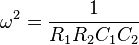
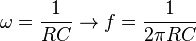
The frequency of oscillation is given by:

Background
Problems with a conventional oscillator
The conventional oscillator circuit is designed so that it will start oscillating ("start up") and that its amplitude will be controlled.
For a linear circuit to oscillate, it must meet the Barkhausen conditions: its loop gain must be one and the phase around the loop must be an integer multiple of 360 degrees. The linear oscillator theory doesn't address how the oscillator starts up or how the amplitude is determined. The linear oscillator can support any amplitude.
In practice, the loop gain is initially larger than unity. Random noise is present in all circuits, and some of that noise will be near the desired frequency. A loop gain greater than one allows the amplitude of frequency to increase exponentially each time around the loop. With a loop gain greater than one, the oscillator will start.
Ideally, the loop gain needs to be just a little bigger than one, but in practice, it is often significantly greater than one. A larger loop gain makes the oscillator start quickly. A large loop gain also compensates for gain variations with temperature and the desired frequency of a tunable oscillator. For the oscillator to start, the loop gain must be greater than one under all possible conditions.
A loop gain greater than one has a down side. In theory, the oscillator amplitude will increase without limit. In practice, the amplitude will increase until the output runs into some limiting factor such as the power supply voltage (the amplifier output runs into the supply rails) or the amplifier output current limits. The limiting reduces the effective gain of the amplifier. (The effect is called gain compression.) In a stable oscillator, the average loop gain will be one.
Although the limiting action stabilizes the output voltage, it has two significant effects: it introduces harmonic distortion and it affects the frequency stability of the oscillator.
The amount of distortion is related to the extra loop gain used for startup. If there's a lot of extra loop gain at small amplitudes, then the gain must decrease more at higher instantaneous amplitudes. That means more distortion.
The amount of distortion is also related to final amplitude of the oscillation. Although an amplifier's gain is ideally linear, in practice it is nonlinear. The nonlinear transcribing function can be viewed as a Taylor series. For small amplitudes, the higher order terms have little effect. For larger amplitudes, the nonlinearity is pronounced. Consequently, for low distortion, the oscillator's output amplitude should be a small fraction of the amplifier's dynamic range.
Bridge oscillator
Meacham proposed a bridge oscillator to address those problems.[4]
Instead of using limiting to set an average gain of 1 around the loop, Meacham proposed a circuit that would set the loop gain to one while the amplifier was still in its linear region. As a result, the distortion would be reduced and the frequency stability would be improved. Meacham designed a quartz crystal oscillator based on a Wheatstone bridge that was a significant improvement over earlier designs.
At the oscillator frequency, Meacham's design was a linear circuit with constant gain. Consequently, there was no distortion of the sine wave. (In practice, an amplifier is not perfectly linear, so there is some distortion, but that distortion is much less than the gain compression approach.)
Hewlett's oscillator
High-gain differential amplifier with positive feedback. The Wien bridge oscillator can be considered as a combination of a differential amplifier and a Wien bridge, connected in a positive feedback loop between the op-amp output and differential input. At the oscillating frequency, the bridge is almost balanced and has very small transfer ratio. The loop gain is a product of the very high op-amp gain and the very low bridge ratio.[5]
Conventional RC oscillator
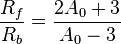
Low-gain single-ended amplifier with positive feedback. Rf, Rb and the op-amp compose a non-inverting amplifier with small gain of 1 + Rf/Rb ≈ 3. R1, R2, C1, C2 compose a bandpass filter. The bandpass filter is connected to provide positive feedback at the frequency of oscillation. In the ideal situation, R1 = R2 = R, C1 = C2 = C and Rf/Rb = 2. Rb self heats and reduces the amplifier gain until the point is reached that there is just enough gain to sustain sinusoidal oscillation without over driving the amplifier.
Wien bridge
Bridge circuits were a common way of measuring component values by comparing them to known values. Often an unknown component would be put in one arm of a bridge, and then the bridge would be nulled by adjusting the other arms or changing the frequency of the voltage source. See, for example, the Wheatstone bridge.
The Wien bridge is one of many common bridges.[6] Wien's bridge is used for precision measurement of capacitance in terms of resistance and frequency.[7] It was also used to measure audio frequencies.
The Wien bridge does not require equal values of R or C. At some frequency, the reactance of the series R2–C2 arm will be an exact multiple of the shunt R1–C1 arm. If the two R3 and R4 arms are adjusted to the same ratio, then the bridge is balanced.
The bridge is balanced when:[8]
 and
and 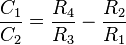
where ω is the radian frequency. ( refers to
  in the figure at top and
  refers to
  .)
.)
The equations simplify if one chooses R1 = R2 and C1 = C2; the result is R4 = 2 R3.
In practice, the values of R and C will never be exactly equal, but the equations above show that for fixed values in the 1 and 2 arms, the bridge will balance at some ω and some ratio of R4/R3.
Analysis
Analyzed from loop gain
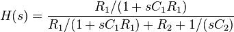
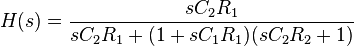
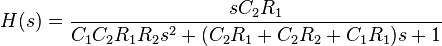
According to Schilling,[5] the loop gain of the Wien bridge oscillator is given by
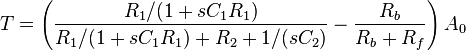
where  is the frequency-dependent gain of the op-amp.
(Note, the component names in Schilling have been replaced with the component names in the figure.)
is the frequency-dependent gain of the op-amp.
(Note, the component names in Schilling have been replaced with the component names in the figure.)
Schilling further says that the condition of oscillation is  .
Which, assuming
.
Which, assuming 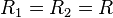 and
and  is satisfied by
and
 with
with 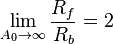
Another analysis, with particular reference to frequency stability and selectivity, will be found in Strauss (1970, p. 671) and Hamilton (2003, p. 449).
Frequency determining network

Let R=R1=R2 and C=C1=C2
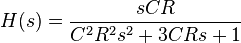
Normalize to CR=1.
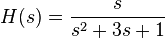
Thus the frequency determining network has a zero at 0 and poles at -1.5±(sqrt(5)/2): -2.6180 and -0.38197. The resulting root locus traces the unit circle. When the gain is 1, the two real poles meet at -1 and split into a complex pair. At gain 3, the poles cross the imaginary axis. At gain 5, the poles meet on the real axis and split into two real poles.
Amplitude stabilization
The key to the Wien bridge oscillator's low distortion oscillation is an amplitude stabilization method that does not use clipping. The idea of using a lamp in a bridge configuration for amplitude stabilization was published by Meacham in 1938.[9] The amplitude of electronic oscillators tends to increase until clipping or other gain limitation is reached. This leads to high harmonic distortion, which is often undesirable.
Hewlett used an incandescent bulb as a power detector, low pass filter and gain control element in the oscillator feedback path to control the output amplitude. The resistance of the light bulb filament (see resistivity article) increases as its temperature increases. The temperature of the filament depends on the power dissipated in the filament and some other factors. If the oscillator's period (an inverse of its frequency) is significantly shorter than the thermal time constant of the filament, then the temperature of the filament will be substantially constant over a cycle. The filament resistance will then determine the amplitude of the output signal. If the amplitude increases, the filament heats up and its resistance increases. The circuit is designed so that a larger filament resistance reduces loop gain, which in turn will reduce the output amplitude. The result is a negative feedback system that stabilizes the output amplitude to a constant value. With this form of amplitude control, the oscillator operates as a near ideal linear system and provides a very low distortion output signal. Oscillators that use limiting for amplitude control often have significant harmonic distortion. At low frequencies, as the time period of the Wien bridge oscillator approaches the thermal time constant of the incandescent bulb, the circuit operation becomes more nonlinear, and the output distortion rises significantly.
Light bulbs have their disadvantages when used as gain control elements in Wien bridge oscillators, most notably a very high sensitivity to vibration due to the bulb's microphonic nature amplitude modulating the oscillator output, a limitation in high frequency response due to the inductive nature of the coiled filament, and current requirements that exceed the capability of many op amps. Modern Wien bridge oscillators have used other nonlinear elements, such as diodes, thermistors, field effect transistors, or photocells for amplitude stabilization in place of light bulbs. Distortion as low as 0.0003% (3 ppm) can be achieved with modern components unavailable to Hewlett.[10]
Wien bridge oscillators that use thermistors also exhibit "amplitude bounce" when the oscillator frequency is changed. This is due to the low damping factor and long time constant of the crude control loop, and disturbances cause the output amplitude to exhibit a decaying sinusoidal response. This can be used as a rough figure of merit, as the greater the amplitude bounce after a disturbance, the lower the output distortion under steady state conditions.
Notes
- ↑ Wien 1891
- ↑ Hewlett 1942
- ↑ Williams (1991, pp. 46–47)
- ↑ Meacham 1938
- ↑ 5.0 5.1 Schilling & Belove (1968, pp. 612–614)
- ↑ Terman 1943, p. 904
- ↑ Terman 1943, p. 904 citing Ferguson & Bartlett 1928
- ↑ Terman 1943, p. 905
- ↑ Meacham 1938. Meacham presented his work at the Thirteenth Annual Convention of Institute of Radio Engineers, New York City, June 16, 1938 and published in Proc. I. R. E. October 1938. BSTJ page 576, states, "This arm has a large positive temperature coefficient of resistance, and is so designed that the portion of the amplifier output which reaches it in the bridge circuit is great enough to raise its temperature and increase its resistance materially. A small tungsten-filament lamp of low wattage rating has been found suitable." Hewlett's patent (filed July 11, 1939) does not mention Meacham and does not show a classic bridge configuration. The circuit in Hewlett's patent also runs the tube's DC plate current through the lamp.
- ↑ Williams (1990, pp. 32–33)
References
- Bauer, Brunton (November 1949), "Design Notes on the Resistance-Capacity Oscillator Circuit (Part I)" (PDF), Hewlett-Packard Journal (Hewlett-Packard Company) 1 (3)
- Bauer, Brunton (December 1949), "Design Notes on the Resistance-Capacity Oscillator Circuit (Part II)" (PDF), Hewlett-Packard Journal (Hewlett-Packard Company) 1 (4)
- Ferguson, J. G.; Bartlett, B. W. (July 1928), "The Measurement of Capacitance in Terms of Resistance and Frequency" (PDF), Bell System Technical Journal 7 (3): 420–437, doi:10.1002/j.1538-7305.1928.tb01234.x
- Hamilton, Scott (2003), An Analog Electronics Companion: basic circuit design for engineers and scientists, Cambridge University Press, ISBN 978-0-521-79838-9
- Hamilton, Scott (2007), An Analog Electronics Companion: basic circuit design for engineers and scientists and introduction to SPICE simulation, Cambridge University Press, ISBN 978-0-521-68780-5
- US 2268872, Hewlett, William R., "Variable Frequency Oscillation Generator", published July 11, 1939, issued January 6, 1942
- Meacham, L. A. (October 1938a), "The Bridge Stabilized Oscillator", Proc. I. R. E. 26: 1278–1294, doi:10.1109/jrproc.1938.228725
- Meacham, L. A. (October 1938), "The Bridge Stabilized Oscillator" (PDF), Bell System Technical Journal 17 (4): 574–591, doi:10.1002/j.1538-7305.1938.tb00799.x. Frequency and amplitude stabilization of an oscillator with no tube overloading. Uses tungsten lamp to balance bridge.
- Oliver, Bernard M. (April–June 1960), "The Effect of μ-Circuit Non-Linearity on the Amplitude Stability of RC Oscillators" (PDF), Hewlett-Packard Journal 11 (8-10): 1–8. Shows that amplifier non-linearity is needed for fast amplitude settling of the Wien bridge oscillator.
- Schilling, Donald; Belove, Charles (1968), Electronic Circuits: Discrete and Integrated, McGraw-Hill
- Strauss, Leonard (1970), Wave Generation and Shaping (2nd ed.), McGraw-Hill, ISBN 978-0-07-062161-9
- Terman, Frederick (1943), Radio Engineers' Handbook, McGraw-Hill
- Wien, M. (1891), "Messung der Inductionsconstanten mit dem "optischen Telephon"" [Measurement of Inductive Constants with the "Optical Telephone"], Annalen der Physik und Chemie (in German) 280 (12): 689–712, Bibcode:1891AnP...280..689W, doi:10.1002/andp.18912801208
- Williams, Jim (June 1990), Bridge Circuits: Marrying Gain and Balance, Application Note 43, Linear Technology Inc, pp. 29–33, 43
- Williams, Jim, ed. (1991), Analog Circuit Design, Art, Science, and Personalities, Butterworth Heinemann, ISBN 0-7506-9640-0
External links
- Model 200A Audio Oscillator, 1939, HP Virtual Museum.
- Wien Bridge Oscillator, including SPICE simulation. The "Wien bridge oscillator" in the simulation is not a low distortion design with amplitude stabilization; it is a more conventional oscillator with a diode limiter.
- Aigrain, P. R.; Williams, E. M. (January 1948), "Theory of Amplitude-Stabilized Oscillators", Proceedings of the IRE 36 (1): 16–19, doi:10.1109/JRPROC.1948.230539
- Online Simulator of Wien Bridge Oscillator – Gives online simulation of wien bridge oscillator.
| ||||||||||||||||||||||||||