Varistor
| Varistor | |
|---|---|
|
A 385-volt metal-oxide varistor | |
| Type | Passive |
| Pin configuration | 2 |
| Electronic symbol | |
 Varistor | |
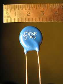

A varistor is an electronic component with an electrical resistivity that varies with the applied voltage.[1] Also known as a voltage-dependent resistor (VDR), it has a nonlinear, non-ohmic current–voltage characteristic that is similar to that of a diode. In contrast to a diode however, it has the same characteristic for both directions of traversing current. At low voltage it has a high electrical resistance which decreases as the voltage is raised.
Varistors are used as control or compensation elements in circuits either to provide optimal operating conditions or to protect against excessive transient voltages. When used as protection devices, they shunt the current created by the excessive voltage away from sensitive components when triggered.
The development of the varistor, in the form of a new type of rectifier (copper oxide), originated in the work by L.O. Grondahl and P.H. Geiger in 1927.[2] The name varistor is a portmanteau of varying resistor. The term is only used for non-ohmic varying resistors. Variable resistors, such as the potentiometer and the rheostat, have ohmic characteristics.
Background
The most common type of varistor is the metal-oxide varistor (MOV). This contains a ceramic mass of zinc oxide grains, in a matrix of other metal oxides (such as small amounts of bismuth, cobalt, manganese) sandwiched between two metal plates (the electrodes). The boundary between each grain and its neighbour forms a diode junction, which allows current to flow in only one direction. The mass of randomly oriented grains is electrically equivalent to a network of back-to-back diode pairs, each pair in parallel with many other pairs.[3] When a small or moderate voltage is applied across the electrodes, only a tiny current flows, caused by reverse leakage through the diode junctions. When a large voltage is applied, the diode junction breaks down due to a combination of thermionic emission and electron tunneling, and a large current flows. The result of this behaviour is a highly nonlinear current-voltage characteristic, in which the MOV has a high resistance at low voltages and a low resistance at high voltages.
A varistor remains non-conductive as a shunt-mode device during normal operation when the voltage across it remains well below its "clamping voltage", thus varistors are typically used for suppressing line voltage surges. However, a varistor may not be able to successfully limit a very large surge from an event like a lightning strike where the energy involved is many orders of magnitude greater than it can handle. Follow-through current resulting from a strike may generate excessive current that completely destroys the varistor. Lesser surges still degrade it, however. Degradation is defined by manufacturer's life-expectancy charts that relate current, time and number of transient pulses. The main parameter affecting varistor life expectancy is its energy (Joule) rating. As the energy rating increases, its life expectancy typically increases exponentially, the number of transient pulses that it can accommodate increases and the "clamping voltage" it provides during each transient decreases. The probability of catastrophic failure can be reduced by increasing the rating, either by using a single varistor of higher rating or by connecting more devices in parallel. A varistor is typically deemed to be fully degraded when its "clamping voltage" has changed by 10%. In this condition it is not visibly damaged and it remains functional (no catastrophic failure).
In general, the primary case of varistor breakdown is localized heating caused as an effect of thermal runaway. This is due to a lack of conformity in individual grain-boundary junctions, which leads to the failure of dominant current paths under thermal stress. If the energy in a transient pulse (normally measured in joules) is too high, the device may melt, burn, vaporize, or otherwise be damaged or destroyed. This (catastrophic) failure occurs when "Absolute Maximum Ratings" in manufacturer's data-sheet are significantly exceeded.
Important parameters are the varistor's energy rating in joules, operating voltage, response time, maximum current, and breakdown (clamping) voltage. Energy rating is often defined using standardized transients such as 8/20 microseconds or 10/1000 microseconds, where 8 microseconds is the transient's front time and 20 microseconds is the time to half value. To protect communications lines (such as telephone lines) transient suppression devices such as 3 mil carbon blocks (IEEE C62.32), ultra-low capacitance varistors or avalanche diodes are used. For higher frequencies such as radio communication equipment, a gas discharge tube (GDT) may be utilized. A typical surge protector power strip is built using MOVs. The cheapest kind may use just one varistor, from hot (live, active) to neutral. A better protector would contain at least three varistors; one across each of the three pairs of conductors (hot-neutral, hot-ground, neutral-ground). A power strip protector in the United States should have a UL1449 3rd edition approval so that catastrophic MOV failure would not create a fire hazard.
Specifications
The response time of the MOV is not standardized. The sub-nanosecond MOV response claim is based on the material's intrinsic response time, but will be slowed down by other factors such as the inductance of component leads and the mounting method. That response time is also qualified as insignificant when compared to a transient having an 8 µs rise-time, thereby allowing ample time for the device to slowly turn-on. When subjected to a very fast, <1 ns rise-time transient, response times for the MOV are in the 40–60 ns range.[4]
Typical capacitance for consumer-sized (7–20 mm diameter) varistors are in the range of 100–1,000 pF. Smaller, lower-capacitance varistors are available with capacitance of ~1 pF for microelectronic protection, such as in cellular phones. These low-capacitance varistors are, however, unable to withstand large surge currents simply due to their compact PCB-mount size. MOVs are specified according to the voltage range that they can tolerate without damage.
Hazards
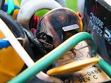
While an MOV is designed to conduct significant power for very short durations (about 8 to 20 microseconds), such as caused by lightning strikes, it typically does not have the capacity to conduct sustained energy. Under normal utility voltage conditions, this is not a problem. However, certain types of faults on the utility power grid can result in sustained over-voltage conditions. Examples include a loss of a neutral conductor or shorted lines on the high voltage system. Application of sustained over-voltage to a MOV can cause high dissipation, potentially resulting in the MOV device catching fire. The National Fire Protection Association (NFPA) has documented many cases of catastrophic fires that have been caused by MOV devices in surge suppressors, and has issued bulletins on the issue.
A series connected thermal fuse is one solution to catastrophic MOV failure. Varistors with internal thermal protection are also available.
There are several issues to be noted regarding behavior of transient voltage surge suppressors (TVSS) incorporating MOVs under over-voltage conditions. Depending on the level of conducted current, dissipated heat may be insufficient to cause failure, but may degrade the MOV device and reduce its life expectancy. If excessive current is conducted by a MOV, it may fail catastrophically, keeping the load connected, but now without any surge protection. A user may have no indication when the surge suppressor has failed. Under the right conditions of over-voltage and line impedance, it may be possible to cause the MOV to burst into flames,[5] the root cause of many fires[6] and the main reason for NFPA’s concern resulting in UL1449 in 1986 and subsequent revisions in 1998 and 2009. Properly designed TVSS devices must not fail catastrophically, resulting in the opening of a thermal fuse or something equivalent that only disconnects MOV devices.
Varistor limitations
A MOV inside a TVSS device does not provide equipment with complete power protection. In particular, a MOV device provides no protection for the connected equipment from sustained over-voltages that may result in damage to that equipment as well as to the protector device. Other sustained and harmful overvoltages may be lower and therefore ignored by a MOV device.
A varistor provides no equipment protection from inrush current surges (during equipment startup), from overcurrent (created by a short circuit), or from voltage sags (also known as a brownout); it neither senses nor affects such events. Susceptibility of electronic equipment to these other power disturbances is defined by other aspects of the system design, either inside the equipment itself or externally by means such as a UPS, a voltage regulator or a surge protector with built-in overvoltage protection (which typically consists of a voltage-sensing circuit and a relay for disconnecting the AC input when the voltage reaches a danger threshold).
Varistors compared to other transient suppressors
Another method for suppressing voltage spikes is the transient-voltage-suppression diode (TVS). Although diodes do not have as much capacity to conduct large surges as MOVs, diodes are not degraded by smaller surges and can be implemented with a lower "clamping voltage". MOVs degrade from repeated exposure to surges[7] and generally have a higher "clamping voltage" so that leakage does not degrade the MOV. Both types are available over a wide range of voltages. MOVs tend to be more suitable for higher voltages, because they can conduct the higher associated energies at less cost.[8]
Another type of transient suppressor is the gas-tube suppressor. This is a type of spark gap that may use air or an inert gas mixture and often, a small amount of radioactive material such as Ni-63, to provide a more consistent breakdown voltage and reduce response time. Unfortunately, these devices may have higher breakdown voltages and longer response times than varistors. However, they can handle significantly higher fault currents and withstand multiple high-voltage hits (for example, from lightning) without significant degradation.
Multi-layer varistor
Multi-layer varistor (MLV) devices provide electrostatic discharge protection to electronic circuits from low to medium energy transients in sensitive equipment operating at 0-120 volts dc. They have peak current ratings from about 20 to 500 amperes, and peak energy ratings from 0.05 to 2.5 joules.
See also
- Resettable fuse, a current-sensitive device
- Trisil
References
- ↑ Bell Laboratories (1983). S. Millman, ed. A History of Engineering and Science in the Bell System, Physical Science (1925-1980) (PDF). AT&T Bell Laboratories. p. 413. ISBN 0932764037.
- ↑ Grondahl, L. O.; Geiger, P. H. (February 1927). "A new electronic rectifier". Journal of the A.I.E.E 46 (3): 357–366. doi:10.1109/JAIEE.1927.6534186.
- ↑ "Introduction to Metal Oxide Varistors" June 5, 2012 on PowerGuru.org
- ↑ "Detailed Comparison of Surge Suppression Devices". Archived from the original on 2010-11-05.
- ↑ "Metal Oxide Varistors | Circuit Breakers Blog - Expert Safety and Usage Information". Circuit Breakers Blog. Retrieved 2013-01-14.
- ↑ http://www.esdjournal.com/techpapr/Pharr/INVESTIGATING%20SURGE%20SUPPRESSOR%20FIRES.doc
- ↑ Winn L. Rosch (2003). Winn L. Rosch Hardware Bible (6th ed.). Que Publishing. p. 1052. ISBN 978-0-7897-2859-3.
- ↑ Brown, Kenneth (March 2004). "Metal Oxide Varistor Degradation". IAEI Magazine. Retrieved 2011-03-30.
- Jaroszewski, M.; Wieczorek, K.; Bretuj, W.; Kostyla, P.; (5–9 July 2004). "Capacitance changes in degraded metal oxide varistors". 2004 International Conference on Solid Dielectrics, Toulouse, France 2: 736. doi:10.1109/ICSD.2004.1350537. ISBN 0-7803-8348-6.
- Jim Pharr. "Surge Suppressor Fires".
External links
| Wikimedia Commons has media related to Varistors. |
- The ABCs of MOVs — application notes from Littelfuse company
- Varistor testing from Littelfuse company
| ||||||||||||||||||||||||||||||||||