Turnstile antenna
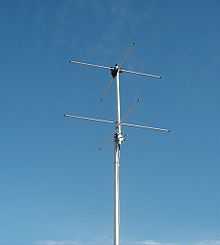
A turnstile antenna is a radio antenna with a set of two dipole antennas aligned at right angles to each other with currents of equal magnitude and in phase quadrature.[1] The name reflects the notion the antenna looks like a turnstile when mounted horizontally.[2] The turnstile antenna is often referred to as crossed dipoles.[3]
History
The turnstile antenna was invented by George Brown in 1935[2] and described in scholarship in 1936.[4] The patent history reveals the popularity of the turnstile antenna over the years.[5]
Turnstile Antenna Characteristics
The antenna can be used in two different modes: Normal Mode and Axial Mode.
Normal Mode
Normal mode, is the original configuration of the turnstile antenna where the orthogonal set of dipoles are each parallel and above the ground. Several sets of the crossed dipoles can be arranged one above the other where each is fed a portion of the RF power.[2] This configuration radiates omnidirectional, horizontally-polarized radio waves in all azimuth directions.[2] The turnstile antenna's azimuth gain pattern would be perfectly circular if each dipole was infinitely short.[1] Practical dipoles yield a pattern departing from perfectly circular by +/- 5 percent.[1]
The full name of the antenna used this way is the George Brown turnstile antenna.[1]
Axial Mode
When used in axial mode each dipole orients perpendicular to the line of communication. The antenna radiates circularly-polarized (CP) radio waves along this axis.[1] A standalone turnstile antenna generates opposite circular polarized signals in each axial direction; For example, right hand in one direction and left hand the other.[3] For this reason, the turnstile crossed dipole pair is often arranged over a conductive reflecting surface.[3] This reflects one axial emission whereby the reflection changes the polarity of the CP adding to the opposite CP emission and reinforcing a stronger CP signal.[3] The conductive reflective surface is sometimes replaced with a set of dipoles arranged like the reflecting elements in a Yagi-Uda antenna.
The axial mode turnstile antenna is often used for satellite communication because, being circularly polarized, the polarization of the signal doesn't rotate when the satellite rotates.
Another use of the axial mode arrangement is with missiles.[6]
Quadrature Currents
The fundamental requirement for the turnstile to function is ensuring each dipole's currents are of equal magnitude and in phase quadrature.[1] This is done with feed-line techniques or by adding reactance in series with the dipoles.[1]
Quadrature Feed
A popular method of feeding the two dipoles in a turnstile antenna involves splitting the RF signal with a two way splitter then delaying one by 90 degrees additional electrical length. Each connects to a dipole resulting in the proper quadrature currents.[1]
Modified Dipole Dimensions
By modifying the length and shape of the dipoles, the combined terminal impedance presented to a single feed-point can achieve pure resistance and yield quadrature currents in each dipole.[1][6] This method of changing the physical dimensions of the antenna element to yield quadrature currents is known as turnstile feeding.[3]
Popular Turnstile Configurations
Horizontal Omni Arrays
The original purpose of the George Brown turnstile antennas was providing a horizontally polarized signal in all directions from a transmitting location.[2] To this end, the original patent describes arranging multiple copies of the basic turnstile cross dipole pair, one above the other and feeding all with RF power.[1][2]
Batwing Arrays
A later innovation involved changing the crossed dipole to a set of orthogonal large area antenna elements.[7] The batwing turnstile is popular for VHF broadcasting.[8] The batwing shape of each element produces an antenna with wide impedance bandwidth.[3] This antenna is most often arranged into vertical arrays similar to the George Brown turnstile array and is well known as the superturnstile antenna.[1][3] The wide bandwidth is beneficial to VHF lowband high bandwidth transmissions such as broadcast television.[3] compared to a lowband VHF version.
Satellite and Missile/Rocket Antenna
The benefits of circular polarization between moving objects justifies considering the axial mode of the turnstile antenna.
The US Nike missile program made use of the axial mode for telemetry and used the modified dipole technique to force the quadrature currents.[6]
External links
- Turnstile Construction plans for satellite communication
- Construction plans
- Turnstile design for APT weather satellite reception
- Radiation of Turnstile Antennas Above a Conducting Ground Plane
References
- ↑ 1.0 1.1 1.2 1.3 1.4 1.5 1.6 1.7 1.8 1.9 1.10 Kraus, John (1988). "16: Antennas for Special Applications: Feeding Applications". Antennas (2nd ed.). McGraw-Hill, Inc. pp. 726–729. ISBN 0-07-035422-7.
- ↑ 2.0 2.1 2.2 2.3 2.4 2.5 Brown, George (1935). "Antenna System". Retrieved 14 January 2014.
- ↑ 3.0 3.1 3.2 3.3 3.4 3.5 3.6 3.7 Milligan, Thomas (2005). "5 - Dipoles, Slots and Loops". Modern Antenna Design (2nd ed.). Hoboken, New Jersey: John Wiley & Sons, Inc. pp. 231–237. ISBN 978-0-471-45776-3.
- ↑ Brown, George (April 1936). "The Turnstile Antenna". Electronics.
- ↑ "Patents about Turnstile Antennas".
- ↑ 6.0 6.1 6.2 Martin, John (1952). "[Missile] Antenna". Retrieved 15 January 2014.
- ↑ Masters, Robert (1945). "[Batwing] Antenna". Retrieved 15 January 2014.
- ↑ Whitaker, Jerry (1996). "Antennas for Specific Applications". In Jerry Whitaker. The Electronics Handbook. CRC Press, Inc. p. 1341. ISBN 0-8493-8345-5.
The turnstile is the earliest and most popular resonant antenna for VHF broadcasting.