Turbofan

| Part of a series on |
| Aircraft propulsion |
|---|
|
Shaft engines: driving propellers, rotors, ducted fans or propfans |
| Reaction engines |
| Others |
.jpg)
.JPG)
The turbofan or fanjet is a type of airbreathing jet engine that is widely used in aircraft propulsion. The word "turbofan" is a portmanteau of "turbine" and "fan": the turbo portion refers to a gas turbine engine which takes mechanical energy from combustion,[1] and the fan, a ducted fan that uses the mechanical energy from the gas turbine to accelerate air rearwards. Thus, whereas all the air taken in by a turbojet passes through the turbine (through the combustion chamber), in a turbofan some of that air bypasses the turbine. A turbofan thus can be thought of as a turbojet being used to drive a ducted fan, with both of those contributing to the thrust. The ratio of the mass-flow of air bypassing the engine core compared to the mass-flow of air passing through the core is referred to as the bypass ratio. The engine produces thrust through a combination of these two portions working in concert; engines that use more jet thrust relative to fan thrust are known as low bypass turbofans, conversely those that have considerably more fan thrust than jet thrust are known as high bypass. Most commercial aviation jet engines in use today are of the high-bypass type, and most modern military fighter engines are low-bypass. Afterburners are not used on high-bypass turbofan engines but may be used on either low-bypass turbofan or turbojet engines.
Most of the air flow through a high-bypass turbofan is low-velocity bypass flow: even when combined with the much higher velocity engine exhaust, the net average exhaust velocity is considerably lower than in a pure turbojet. Engine noise is largely a function of exhaust velocity, therefore turbofan engines are significantly quieter than a pure-jet of the same thrust. Other factors include turbine blade and exhaust outlet geometries, such as noise-reducing "chevrons" seen on the Rolls-Royce Trent 1000 and General Electric GEnx engines used on the Boeing 787.
Since the efficiency of propulsion is a function of the relative airspeed of the exhaust to the surrounding air, propellers are most efficient for low speed, pure jets for high speeds, and ducted fans in the middle. Turbofans are thus the most efficient engines in the range of speeds from about 500 to 1,000 km/h (310 to 620 mph), the speed at which most commercial aircraft operate.[2][3] Turbofans retain an efficiency edge over pure jets at low supersonic speeds up to roughly Mach 1.6, but have also been found to be efficient when used with continuous afterburner at Mach 3 and above.
The vast majority of turbofans follow the same basic design, with a large fan at the front of the engine and a relatively small jet engine behind it. There have been a number of variations on this design, however, including rear-mounted fans which can easily be added to an existing pure-jet design, or designs that combine a low-pressure turbine and a fan stage in a single rear-mounted unit.
Early turbofans
_used_in_Boeing_707-420_at_Flugausstellung_Hermeskeil%2C_pic1.JPG)

Early turbojet engines were very fuel-inefficient, as their overall pressure ratio and turbine inlet temperature were severely limited by the technology available at the time. In 1939-1941 Soviet designer Arkhip Lyulka elaborated the design for the World's first turbofan engine, and acquired a patent for this new invention on April 22, 1941. Although several prototypes were built and ready for state tests, Lyulka was in 1941 forced to abandon his research and evacuate to the Urals following the Nazi invasion of the Soviet Union. So the first tested turbofan was apparently the German Daimler-Benz DB 670 (designated as the 109-007 by the RLM) which was operated on its testbed on April 1, 1943. The engine was abandoned later while the war went on and problems could not be solved. The British wartime Metrovick F.2 axial flow jet was given a fan, as the Metrovick F.3 in 1943, to create the first British turbofan.[4]
Improved materials, and the introduction of twin compressors such as in the Bristol Olympus[5] and the later Pratt & Whitney JT3C engine, increased the overall pressure ratio and thus the thermodynamic efficiency of engines, but they also led to a poor propulsive efficiency, as pure turbojets have a high specific thrust/high velocity exhaust better suited to supersonic flight.
The original low-bypass turbofan engines were designed to improve propulsive efficiency by reducing the exhaust velocity to a value closer to that of the aircraft. The Rolls-Royce Conway, the world's first production turbofan, had a bypass ratio of 0.3, similar to the modern General Electric F404 fighter engine. Civilian turbofan engines of the 1960s, such as the Pratt & Whitney JT8D and the Rolls-Royce Spey had bypass ratios closer to 1, but were not dissimilar to their military equivalents.
The unusual General Electric CF700 turbofan engine was developed as an aft-fan engine with a 2.0 bypass ratio. This was derived from the General Electric J85/CJ610 turbojet (2,850 lbf or 12,650 N) to power the larger Rockwell Sabreliner 75/80 model aircraft, as well as the Dassault Falcon 20 with about a 50% increase in thrust (4,200 lbf or 18,700 N). The CF700 was the first small turbofan in the world to be certified by the Federal Aviation Administration (FAA). There are now over 400 CF700 aircraft in operation around the world, with an experience base of over 10 million service hours. The CF700 turbofan engine was also used to train Moon-bound astronauts in Project Apollo as the powerplant for the Lunar Landing Research Vehicle. The CJ805-23 was a similar, but larger, design.
Low-bypass turbofan

A high specific thrust/low bypass ratio turbofan normally has a multi-stage fan, developing a relatively high pressure ratio and, thus, yielding a high (mixed or cold) exhaust velocity. The core airflow needs to be large enough to give sufficient core power to drive the fan. A smaller core flow/higher bypass ratio cycle can be achieved by raising the (HP) turbine rotor inlet temperature.
Imagine a retrofit situation where a new low bypass ratio, mixed exhaust, turbofan is replacing an old turbojet, in a particular military application. Say the new engine is to have the same airflow and net thrust (i.e. same specific thrust) as the one it is replacing. A bypass flow can only be introduced if the turbine inlet temperature is allowed to increase, to compensate for a correspondingly smaller core flow. Improvements in turbine cooling/material technology would facilitate the use of a higher turbine inlet temperature, despite increases in cooling air temperature, resulting from a probable increase in overall pressure ratio.
Efficiently done, the resulting turbofan would probably operate at a higher nozzle pressure ratio than the turbojet, but with a lower exhaust temperature to retain net thrust. Since the temperature rise across the whole engine (intake to nozzle) would be lower, the (dry power) fuel flow would also be reduced, resulting in a better specific fuel consumption (SFC).
A few low-bypass ratio military turbofans (e.g., F404) have Variable Inlet Guide Vanes, with piano-style hinges, to direct air onto the first rotor stage. This improves the fan surge margin (see compressor map) in the mid-flow range. The swing wing F-111 achieved a very high range/payload capability by pioneering this, and it was also the heart of the famous F-14 Tomcat air superiority fighter which used the same engines in a smaller, more agile airframe to achieve efficient cruise and Mach 2 speed.
Afterburning turbofan

Since the 1970s, most jet fighter engines have been low/medium bypass turbofans with a mixed exhaust, afterburner and variable area final nozzle. An afterburner is a combustor located downstream of the turbine blades and directly upstream of the nozzle, which burns fuel from afterburner-specific fuel injectors. When lit, prodigious amounts of fuel are burnt in the afterburner, raising the temperature of exhaust gases by a significant degree, resulting in a higher exhaust velocity/engine specific thrust. The variable geometry nozzle must open to a larger throat area to accommodate the extra volume flow when the afterburner is lit. Afterburning is often designed to give a significant thrust boost for take off, transonic acceleration and combat maneuvers, but is very fuel intensive. Consequently afterburning can only be used for short portions of a mission.
Unlike the main combustor, where the downstream turbine blades must not be damaged by high temperatures, an afterburner can operate at the ideal maximum (stoichiometric) temperature (i.e., about 2100K/3780Ra/3320F). At a fixed total applied fuel:air ratio, the total fuel flow for a given fan airflow will be the same, regardless of the dry specific thrust of the engine. However, a high specific thrust turbofan will, by definition, have a higher nozzle pressure ratio, resulting in a higher afterburning net thrust and, therefore, a lower afterburning specific fuel consumption (SFC). However, high specific thrust engines have a high dry SFC. The situation is reversed for a medium specific thrust afterburning turbofan: i.e., poor afterburning SFC/good dry SFC. The former engine is suitable for a combat aircraft which must remain in afterburning combat for a fairly long period, but only has to fight fairly close to the airfield (e.g. cross border skirmishes) The latter engine is better for an aircraft that has to fly some distance, or loiter for a long time, before going into combat. However, the pilot can only afford to stay in afterburning for a short period, before aircraft fuel reserves become dangerously low.
Modern low-bypass military turbofans include the Pratt & Whitney F119, the Eurojet EJ200, the General Electric F110, the Klimov RD-33, and the Saturn AL-31, all of which feature a mixed exhaust, afterburner and variable area propelling nozzle.
High-bypass turbofan
A. Low-pressure spool
B. High-pressure spool
C. Stationary components
1. Nacelle
2. Fan
3. Low-pressure compressor
4. High-pressure compressor
5. Combustion chamber
6. High-pressure turbine
7. Low-pressure turbine
8. Core nozzle
9. Fan nozzle
The low specific thrust/high bypass ratio turbofans used in today's civil jetliners (and some military transport aircraft) evolved from the high specific thrust/low bypass ratio turbofans used in such [production] aircraft back in the 1960s.
Low specific thrust is achieved by replacing the multi-stage fan with a single-stage unit. Unlike some military engines, modern civil turbofans do not have any stationary inlet guide vanes in front of the fan rotor. The fan is scaled to achieve the desired net thrust.
The core (or gas generator) of the engine must generate sufficient core power to at least drive the fan at its design flow and pressure ratio. Through improvements in turbine cooling/material technology, a higher (HP) turbine rotor inlet temperature can be used, thus facilitating a smaller (and lighter) core and (potentially) improving the core thermal efficiency. Reducing the core mass flow tends to increase the load on the LP turbine, so this unit may require additional stages to reduce the average stage loading and to maintain LP turbine efficiency. Reducing core flow also increases bypass ratio (5:1, or more, is now common).
Further improvements in core thermal efficiency can be achieved by raising the overall pressure ratio of the core. Improved blade aerodynamics reduces the number of extra compressor stages required. With multiple compressors (i.e., LPC, IPC, and HPC) dramatic increases in overall pressure ratio have become possible. Variable geometry (i.e., stators) enable high-pressure-ratio compressors to work surge-free at all throttle settings.

The first high-bypass conventional turbofan engine - the earlier Bristol Siddeley Pegasus was a specialised VTOL engine - was the General Electric TF39, designed in mid 1960s to power the Lockheed C-5 Galaxy military transport aircraft.[3] The civil General Electric CF6 engine used a derived design. Other high-bypass turbofans are the Pratt & Whitney JT9D, the three-shaft Rolls-Royce RB211 and the CFM International CFM56; also the smaller TF34. More recent large high-bypass turbofans include the Pratt & Whitney PW4000, the three-shaft Rolls-Royce Trent, the General Electric GE90/GEnx and the GP7000, produced jointly by GE and P&W.
For reasons of fuel economy, and also of reduced noise, almost all of today's jet airliners are powered by high-bypass turbofans. Although modern combat aircraft tend to use low bypass ratio turbofans, military transport aircraft (e.g., C-17 ) mainly use high bypass ratio turbofans (or turboprops) for fuel efficiency.
The higher the bypass ratio of a turbofan, the lower the mean jet outlet velocity, which in turn translates into high thrust lapse rates (decreasing thrust with increasing speed). Therefore, engines capable of considerably high flight speeds (e.g., Mach 0.83) generate relatively high thrust at low speed or at idle. Among others, this increases runway performance.
The turbofans on twin engined airliners are further more powerful to cope with losing one engine during take-off, which reduces the aircraft's net thrust by half. Modern twin engined airliners normally climb very steeply immediately after take-off. If one engine is lost, the climb-out is much shallower, but sufficient to clear obstacles in the flightpath.
The Soviet Union's engine technology was less advanced than the West's and its first wide-body aircraft, the Ilyushin Il-86, was powered by low-bypass engines. The Yakovlev Yak-42, a medium-range, rear-engined aircraft seating up to 120 passengers introduced in 1980 was the first Soviet aircraft to use high-bypass engines.
Turbofan configurations
Turbofan engines come in a variety of engine configurations. For a given engine cycle (i.e., same airflow, bypass ratio, fan pressure ratio, overall pressure ratio and HP turbine rotor inlet temperature), the choice of turbofan configuration has little impact upon the design point performance (e.g., net thrust, SFC), as long as overall component performance is maintained. Off-design performance and stability is, however, affected by engine configuration.
As the design overall pressure ratio of an engine cycle increases, it becomes more difficult to throttle the compression system, without encountering an instability known as compressor surge. This occurs when some of the compressor aerofoils stall (like the wings of an aircraft) causing a violent change in the direction of the airflow. However, compressor stall can be avoided, at throttled conditions, by progressively:
1) opening interstage/intercompressor blow-off valves (inefficient)
and/or
2) closing variable stators within the compressor
Most modern American civil turbofans employ a relatively high-pressure-ratio high-pressure (HP) compressor, with many rows of variable stators to control surge margin at part-throttle. In the three-spool RB211/Trent the core compression system is split into two, with the IP compressor, which supercharges the HP compressor, being on a different coaxial shaft and driven by a separate (IP) turbine. As the HP compressor has a modest pressure ratio it can be throttled-back surge-free, without employing variable geometry. However, because a shallow IP compressor working line is inevitable, the IPC has one stage of variable geometry on all variants except the -535, which has none.[6]
Single-shaft turbofan
Although far from common, the single-shaft turbofan is probably the simplest configuration, comprising a fan and high-pressure compressor driven by a single turbine unit, all on the same shaft. The SNECMA M53, which powers Mirage fighter aircraft, is an example of a single-shaft turbofan. Despite the simplicity of the turbomachinery configuration, the M53 requires a variable area mixer to facilitate part-throttle operation.
Aft-fan turbofan
One of the earliest turbofans was a derivative of the General Electric J79 turbojet, known as the CJ805-23, which featured an integrated aft fan/low-pressure (LP) turbine unit located in the turbojet exhaust jetpipe. Hot gas from the turbojet turbine exhaust expanded through the LP turbine, the fan blades being a radial extension of the turbine blades. This aft-fan configuration was later exploited in the General Electric GE-36 UDF (propfan) Demonstrator of the early 80s. One of the problems with the aft fan configuration is hot gas leakage from the LP turbine to the fan.
Basic two spool
Many turbofans have the basic two-spool configuration where both the fan and LP turbine (i.e., LP spool) are mounted on a second (LP) shaft, running concentrically with the HP spool (i.e., HP compressor driven by HP turbine). The BR710 is typical of this configuration. At the smaller thrust sizes, instead of all-axial blading, the HP compressor configuration may be axial-centrifugal (e.g., General Electric CFE738), double-centrifugal or even diagonal/centrifugal (e.g., Pratt & Whitney Canada PW600).
Boosted two spool
Higher overall pressure ratios can be achieved by either raising the HP compressor pressure ratio or adding an intermediate-pressure (IP) Compressor between the fan and HP compressor, to supercharge or boost the latter unit helping to raise the overall pressure ratio of the engine cycle to the very high levels employed today (i.e., greater than 40:1, typically). All of the large American turbofans (e.g., General Electric CF6, GE90 and GEnx plus Pratt & Whitney JT9D and PW4000) feature an IP compressor mounted on the LP shaft and driven, like the fan, by the LP turbine, the mechanical speed of which is dictated by the tip speed and diameter of the fan. The Rolls-Royce BR715 is a non-American example of this. The high bypass ratios (i.e., fan duct flow/core flow) used in modern civil turbofans tends to reduce the relative diameter of the attached IP compressor, causing its mean tip speed to decrease. Consequently more IPC stages are required to develop the necessary IPC pressure rise.
Three spool
Rolls-Royce chose a three spool configuration for their large civil turbofans (i.e., the RB211 and Trent families), where the intermediate pressure (IP) compressor is mounted on a separate (IP) shaft, running concentrically with the LP and HP shafts, and is driven by a separate IP turbine. The first three spool engine was the earlier Rolls-Royce RB.203 Trent of 1967.
Ivchenko Design Bureau chose the same configuration for their Lotarev D-36 engine, followed by Lotarev/Progress D-18T and Progress D-436.
The Turbo-Union RB199 military turbofan also has a three spool configuration, as do the military Kuznetsov NK-25 and NK-321.
Geared fan

As bypass ratio increases, the mean radius ratio of the fan and low-pressure turbine (LPT) increases. Consequently, if the fan is to rotate at its optimum blade speed the LPT blading will spin slowly, so additional LPT stages will be required, to extract sufficient energy to drive the fan. Introducing a (planetary) reduction gearbox, with a suitable gear ratio, between the LP shaft and the fan enables both the fan and LP turbine to operate at their optimum speeds. Typical of this configuration are the long-established Honeywell TFE731, the Honeywell ALF 502/507, and the recent Pratt & Whitney PW1000G.
Military turbofans

Most of the configurations discussed above are used in civilian turbofans, while modern military turbofans (e.g., SNECMA M88) are usually basic two-spool.
High-pressure turbine
Most civil turbofans use a high-efficiency, 2-stage HP turbine to drive the HP compressor. The CFM56 uses an alternative approach: a single-stage, high-work unit. While this approach is probably less efficient, there are savings on cooling air, weight and cost. In the RB211 and Trent series, Rolls-Royce split the two stages into two discrete units; one on the HP shaft driving the HP compressor; the other on the IP shaft driving the IP (intermediate pressure) compressor. Modern military turbofans tend to use single-stage HP turbines.
Low-pressure turbine
Modern civil turbofans have multi-stage LP turbines (e.g., 3, 4, 5, 6, 7). The number of stages required depends on the engine cycle bypass ratio and how much supercharging (i.e., IP compression) is on the LP shaft, behind the fan. A geared fan may reduce the number of required LPT stages in some applications.[7] Because of the much lower bypass ratios employed, military turbofans only require one or two LP turbine stages.
Cycle improvements
Consider a mixed turbofan with a fixed bypass ratio and airflow. Increasing the overall pressure ratio of the compression system raises the combustor entry temperature. Therefore, at a fixed fuel flow there is an increase in (HP) turbine rotor inlet temperature. Although the higher temperature rise across the compression system implies a larger temperature drop over the turbine system, the mixed nozzle temperature is unaffected, because the same amount of heat is being added to the system. There is, however, a rise in nozzle pressure, because overall pressure ratio increases faster than the turbine expansion ratio, causing an increase in the hot mixer entry pressure. Consequently, net thrust increases, whilst specific fuel consumption (fuel flow/net thrust) decreases. A similar trend occurs with unmixed turbofans.
So turbofans can be made more fuel efficient by raising overall pressure ratio and turbine rotor inlet temperature in unison. However, better turbine materials and/or improved vane/blade cooling are required to cope with increases in both turbine rotor inlet temperature and compressor delivery temperature. Increasing the latter may require better compressor materials.
Overall pressure ratio can be increased by improving fan (or) LP compressor pressure ratio and/or HP compressor pressure ratio. If the latter is held constant, the increase in (HP) compressor delivery temperature (from raising overall pressure ratio) implies an increase in HP mechanical speed. However, stressing considerations might limit this parameter, implying, despite an increase in overall pressure ratio, a reduction in HP compressor pressure ratio.
According to simple theory, if the ratio of turbine rotor inlet temperature/(HP) compressor delivery temperature is maintained, the HP turbine throat area can be retained. However, this assumes that cycle improvements are obtained, while retaining the datum (HP) compressor exit flow function (non-dimensional flow). In practice, changes to the non-dimensional speed of the (HP) compressor and cooling bleed extraction would probably make this assumption invalid, making some adjustment to HP turbine throat area unavoidable. This means the HP turbine nozzle guide vanes would have to be different from the original. In all probability, the downstream LP turbine nozzle guide vanes would have to be changed anyway.
Thrust growth
Thrust growth is obtained by increasing core power. There are two basic routes available:
- hot route: increase HP turbine rotor inlet temperature
- cold route: increase core mass flow
Both routes require an increase in the combustor fuel flow and, therefore, the heat energy added to the core stream.
The hot route may require changes in turbine blade/vane materials and/or better blade/vane cooling. The cold route can be obtained by one of the following:
- adding T-stages to the LP/IP compression
- adding a zero-stage to the HP compression
- improving the compression process, without adding stages (e.g. higher fan hub pressure ratio)
all of which increase both overall pressure ratio and core airflow.
Alternatively, the core size can be increased, to raise core airflow, without changing overall pressure ratio. This route is expensive, since a new (upflowed) turbine system (and possibly a larger IP compressor) is also required.
Changes must also be made to the fan to absorb the extra core power. On a civil engine, jet noise considerations mean that any significant increase in Take-off thrust must be accompanied by a corresponding increase in fan mass flow (to maintain a T/O specific thrust of about 30 lbf/lb/s). To reduce noise civilian turbofans have a specially shaped nozzle that limits the exhaust speed to subsonic speeds. This leads to a thermic clogging termed choked nozzle where the mass flow cannot be increased beyond a certain amount. Thus, the mass flow can only be increased through the bypass airstream, usually by increasing fan diameter. On military engines, the fan pressure ratio would probably be increased to improve specific thrust, jet noise not normally being an important factor.
Technical discussion
- Specific Thrust (net thrust/intake airflow) is an important parameter for turbofans and jet engines in general. Imagine a fan (driven by an appropriately sized electric motor) operating within a pipe, which is connected to a propelling nozzle. It is fairly obvious, the higher the Fan Pressure Ratio (fan discharge pressure/fan inlet pressure), the higher the jet velocity and the corresponding specific thrust. Now imagine we replace this set-up with an equivalent turbofan - same airflow and same fan pressure ratio. Obviously, the core of the turbofan must produce sufficient power to drive the fan via the Low Pressure (LP) Turbine. If we choose a low (HP) Turbine Inlet Temperature for the gas generator, the core airflow needs to be relatively high to compensate. The corresponding bypass ratio is therefore relatively low. If we raise the Turbine Inlet Temperature, the core airflow can be smaller, thus increasing bypass ratio. Raising turbine inlet temperature tends to increase thermal efficiency and, therefore, improve fuel efficiency.
- Naturally, as altitude increases there is a decrease in air density and, therefore, the net thrust of an engine. There is also a flight speed effect, termed Thrust Lapse Rate. Consider the approximate equation for net thrust again:

With a high specific thrust (e.g., fighter) engine, the jet velocity is relatively high, so intuitively one can see that increases in flight velocity have less of an impact upon net thrust than a medium specific thrust (e.g., trainer) engine, where the jet velocity is lower. The impact of thrust lapse rate upon a low specific thrust (e.g., civil) engine is even more severe. At high flight speeds, high-specific-thrust engines can pick up net thrust through the ram rise in the intake, but this effect tends to diminish at supersonic speeds because of shock wave losses. - Thrust growth on civil turbofans is usually obtained by increasing fan airflow, thus preventing the jet noise becoming too high. However, the larger fan airflow requires more power from the core. This can be achieved by raising the Overall Pressure Ratio (combustor inlet pressure/intake delivery pressure) to induce more airflow into the core and by increasing turbine inlet temperature. Together, these parameters tend to increase core thermal efficiency and improve fuel efficiency.
- Some high bypass ratio civil turbofans use an extremely low area ratio (less than 1.01), convergent-divergent, nozzle on the bypass (or mixed exhaust) stream, to control the fan working line. The nozzle acts as if it has variable geometry. At low flight speeds the nozzle is unchoked (less than a Mach Number of unity), so the exhaust gas speeds up as it approaches the throat and then slows down slightly as it reaches the divergent section. Consequently, the nozzle exit area controls the fan match and, being larger than the throat, pulls the fan working line slightly away from surge. At higher flight speeds, the ram rise in the intake increases nozzle pressure ratio to the point where the throat becomes choked (M=1.0). Under these circumstances, the throat area dictates the fan match and, being smaller than the exit, pushes the fan working line slightly towards surge. This is not a problem, since fan surge margin is much better at high flight speeds.
- The off-design behaviour of turbofans is illustrated under compressor map and turbine map.
- Because modern civil turbofans operate at low specific thrust, they only require a single fan stage to develop the required fan pressure ratio. The desired overall pressure ratio for the engine cycle is usually achieved by multiple axial stages on the core compression. Rolls-Royce tend to split the core compression into two with an intermediate pressure (IP) supercharging the HP compressor, both units being driven by turbines with a single stage, mounted on separate shafts. Consequently, the HP compressor need only develop a modest pressure ratio (e.g., ~4.5:1). US civil engines use much higher HP compressor pressure ratios (e.g., ~23:1 on the General Electric GE90) and tend to be driven by a two-stage HP turbine. Even so, there are usually a few IP axial stages mounted on the LP shaft, behind the fan, to further supercharge the core compression system. Civil engines have multi-stage LP turbines, the number of stages being determined by the bypass ratio, the amount of IP compression on the LP shaft and the LP turbine blade speed.
- Because military engines usually have to be able to fly very fast at Sea Level, the limit on HP compressor delivery temperature is reached at a fairly modest design overall pressure ratio, compared with that of a civil engine. Also the fan pressure ratio is relatively high, to achieve a medium to high specific thrust. Consequently, modern military turbofans usually only have 5 or 6 HP compressor stages and only require a single-stage HP turbine. Low bypass ratio military turbofans usually have one LP turbine stage, but higher bypass ratio engines need two stages. In theory, by adding IP compressor stages, a modern military turbofan HP compressor could be used in a civil turbofan derivative, but the core would tend to be too small for high thrust applications.
Engine Noise
Turbofan engine noise propagates both upstream the inlet and downstream the primary nozzle and the by-pass duct. The main noise sources are the turbine and the compressor, the jet and the fan. The contribution of each noise source significantly evolved in the last decades:[8] in typical 1960s design the jet was the main source whereas in modern turbofans the fan is the main noise source.
The fan noise is a tonal noise and its signature depends on the fan rotational speed:
- at low speed, the fan noise is due to the interaction of the blades with the distorted flow injected in the engine; This happens for example during the approach;
- at high engine ratings, the fan tip is supersonic and this allows intense rotor-locked duct modes to propagate upstream. This noise is known as "buzz saw" and is typical at take-off.[9]
All modern turbofan engines are equipped with Acoustic liners to damp the noise generated. These are installed in the nacelle they extend as much as possible to cover the largest area. The acoustic performance of the engine can be experimentally evaluated by means of ground tests[10] or in dedicated experimental test rigs.[11]
Recent developments in blade technology
The turbine blades in a turbofan engine are subject to high heat and stress, and require special fabrication. New material construction methods and material science have allowed blades, which were originally polycrystalline (regular metal), to be made from lined up metallic crystals and more recently mono-crystalline (i.e., single crystal) blades, which can operate at higher temperatures with less distortion.
Nickel-based superalloys are used for HP turbine blades in almost all modern jet engines. The temperature capabilities of turbine blades have increased mainly through four approaches: the manufacturing (casting) process, cooling path design, thermal barrier coating (TBC), and alloy development.
Although turbine blade (and vane) materials have improved over the years, much of the increase in (HP) turbine inlet temperatures is due to improvements in blade/vane cooling technology. Relatively cool air is bled from the compression system, bypassing the combustion process, and enters the hollow blade or vane. The gas temperature can therefore be even higher than the melting temperature of the blade.[12] After picking up heat from the blade/vane, the cooling air is dumped into the main gas stream. If the local gas temperatures are low enough, downstream blades/vanes are uncooled and not adversely affected.
Strictly speaking, cycle-wise the HP Turbine Rotor Inlet Temperature (after the temperature drop across the HPT stator) is more important than the (HP) turbine inlet temperature. Although some modern military and civil engines have peak RITs of the order of 1,560 °C (2,840 °F), such temperatures are only experienced for a short time (during take-off) on civil engines.
Turbofan engine manufacturers
The turbofan engine market is dominated by General Electric, Rolls-Royce plc and Pratt & Whitney, in order of market share. GE and SNECMA of France have a joint venture, CFM International. Pratt & Whitney also have a joint venture, International Aero Engines with Japanese Aero Engine Corporation and MTU of Germany, specializing in engines for the Airbus A320 family. Pratt & Whitney and General Electric have a joint venture, Engine Alliance selling a range of engines for aircraft such as the Airbus A380.
General Electric
GE Aviation, part of the General Electric Conglomerate, currently has the largest share of the turbofan engine market. Some of their engine models include the CF6 (available on the Boeing 767, Boeing 747, Airbus A330 and more), GE90 (only the Boeing 777) and GEnx (developed for the Boeing 747-8 & Boeing 787 Dreamliner and proposed for the Airbus A350, currently in development) engines. On the military side, GE engines power many U.S. military aircraft, including the F110, powering 80% of the US Air Force's F-16 Fighting Falcons, and the F404 and F414 engines, which power the Navy's F/A-18 Hornet and Super Hornet. Rolls-Royce and General Electric were jointly developing the F136 engine to power the Joint Strike Fighter, however, due to government budget cuts, the program has been eliminated.
Rolls-Royce
Rolls-Royce plc is the second largest manufacturer of turbofans and is most noted for their RB211 and Trent series, as well as their joint venture engines for the Airbus A320 and McDonnell Douglas MD-90 families (IAE V2500 with Pratt & Whitney and others), the Panavia Tornado (Turbo-Union RB199) and the Boeing 717 (BR700). The Rolls-Royce AE 3007, developed by Allison Engine Company before its acquisition by Rolls-Royce, powers several Embraer regional jets. Rolls-Royce Trent 970s were the first engines to power the new Airbus A380. The famous thrust vectoring Pegasus - actually a Bristol Siddeley design taken on by Rolls-Royce when they took over that company - is the primary powerplant of the Harrier "Jump Jet" and its derivatives.
Pratt & Whitney
Pratt & Whitney is third behind GE and Rolls-Royce in market share. The JT9D has the distinction of being chosen by Boeing to power the original Boeing 747 "Jumbo jet". The PW4000 series is the successor to the JT9D, and powers some Airbus A310, Airbus A300, Boeing 747, Boeing 767, Boeing 777, Airbus A330 and MD-11 aircraft. The PW4000 is certified for 180-minute ETOPS when used in twinjets. The first family has a 94-inch (2.4 m) fan diameter and is designed to power the Boeing 767, Boeing 747, MD-11, and the Airbus A300. The second family is the 100 inch (2.5 m) fan engine developed specifically for the Airbus A330 twinjet, and the third family has a diameter of 112-inch (2.8 m) designed to power Boeing 777. The Pratt & Whitney F119 and its derivative, the F135, power the United States Air Force's F-22 Raptor and the international F-35 Lightning II, respectively. Rolls-Royce are responsible for the lift fan which will provide the F-35B variants with a STOVL capability. The F100 engine was first used on the F-15 Eagle and F-16 Fighting Falcon. Newer Eagles and Falcons also come with GE F110 as an option, and the two are in competition.
CFM International
CFM International is a joint venture between GE Aircraft Engines and SNECMA of France. They have created the very successful CFM56 series, used on Boeing 737, Airbus A340, and Airbus A320 family aircraft.
Engine Alliance
Engine Alliance is a 50/50 joint venture between General Electric and Pratt & Whitney formed in August 1996 to develop, manufacture, sell, and support a family of modern technology aircraft engines for new high-capacity, long-range aircraft.[13] The main application for such an engine, the GP7200, was originally the Boeing 747-500/600X projects, before these were cancelled owing to lack of demand from airlines. Instead, the GP7000 has been re-optimised for use on the Airbus A380 superjumbo. In that market it is competing with the Rolls-Royce Trent 900, the launch engine for the aircraft. The two variants are the GP7270 and the GP7277.
International Aero Engines
International Aero Engines is a Zürich-registered joint venture between Pratt & Whitney, MTU Aero Engines and Japanese Aero Engine Corporation. The collaboration produced the V2500, the second most successful commercial jet engine program in production today in terms of volume, and the third most successful commercial jet engine program in aviation history.[14]
Williams International
Williams International is a manufacturer of small gas turbine engines based in Walled Lake, Michigan, United States. It produces jet engines for cruise missiles and small jet-powered aircraft. They have been producing engines since the 1970s and the range produces between 1000 and 3600 pounds of thrust. The engines are used as original equipment on the Cessna CitationJet CJ1 through CJ4 and Cessna Mustang, Beechcraft 400XPR and Premier 1a and there are several development programs with other manufacturers. The range is also very popular with the re-engine market being used by Sierra Jet and Nextant to breath new life into aging platforms.
Honeywell Aerospace
Honeywell Aerospace is one of the largest manufacturer of aircraft engines and avionics,[15] as well as a producer of auxiliary power units (APUs) and other aviation products. Headquartered in Phoenix, Arizona, it is a division of the Honeywell International conglomerate. Honeywell/ITEC F124 series is used in military jets, such as the Aero L-159 Alca and the Alenia Aermacchi M-346. The Honeywell HTF700 series is used in the Bombardier Challenger 300[16] and the Gulfstream G280.[17] The ALF502 and LF507 turbofans are produced by a partnership between Honeywell and China's state-owned Industrial Development Corporation. The partnership is called the International Turbine Engine Co.[18]
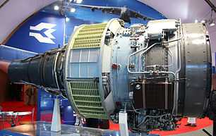
Aviadvigatel
Aviadvigatel is a Russian manufacturer of aircraft engines that succeeded the Soviet Soloviev Design Bureau. The company currently offers[19] several versions of the Aviadvigatel PS-90 engine that powers Ilyushin Il-96-300/400/400T, Tupolev Tu-204, Tu-214 series and the Ilyushin Il-76-MD-90. The company is also developing the new Aviadvigatel PD-14 engine for the new Russian MS-21 airliner.[20]
Ivchenko-Progress
Ivchenko-Progress is the Ukrainian aircraft engine company that succeeded the Soviet Ivchenko Design Bureau. Some of their engine models include Progress D-436 available on the Antonov An-72/74, Yakovlev Yak-42, Beriev Be-200, Antonov An-148 and Tupolev Tu-334 and Progress D-18T that powers two of the world's largest airplanes, Antonov An-124 and Antonov An-225.
NPO Saturn
NPO Saturn is a Russian aircraft engine manufacturer, formed from the mergers of Rybinsk and Lyul'ka-Saturn. Saturn's engines include Lyulka AL-31, Lyulka AL-41, NPO Saturn AL-55 and power many former Eastern Bloc aircraft, such as the Tupolev Tu-154. Saturn holds a 50% stake in the PowerJet joint venture with Snecma.
PowerJet
PowerJet is a 50-50 joint venture between Snecma (Safran) and NPO Saturn, created in July 2004. The company manufactures SaM146, the sole powerplant for the Sukhoi Superjet 100.
Klimov
Klimov was formed in the early 1930s to produce and improve upon the liquid-cooled Hispano-Suiza 12Y V-12 piston engine for which the USSR had acquired a license. Currently, Klimov is the manufacturer of the Klimov RD-33 turbofan engines.
EuroJet
EuroJet Turbo GmbH is a multi-national consortium, the partner companies of which are Rolls Royce of the United Kingdom, Avio of Italy, ITP of Spain and MTU Aero Engines of Germany. Eurojet GmbH was formed in 1986 to manage the development, production, support, maintenance, support and sales of the EJ200 turbofan engine for the Eurofighter Typhoon.[21]
Chinese Turbofans
Three Chinese corporations build turbofan engines. Some of these are licensed or reverse engineered versions of European and Russian turbofans, and the other are indigenous models, but all are in development phase. Shenyang Aircraft Corporation (manufacturer of Shenyang WS-10), Xi'an Aero-Engine Corporation (manufacturer of Xian WS-15) and Guizhou Aircraft Industry Corporation (manufacturer of Guizhou WS-13) manufacture turbofans.
Japanese Turbofans
Three Japanese corporations build turbofan engines. One of these is Mitsubishi Heavy Industries, that manufactured under license the Pratt & Whitney JT8D turbofan for the Kawasaki C-1 military transport aircraft. The others are Kawasaki Heavy Industries and Ishikawajima-Harima Heavy Industries.
Gas Turbine Research Establishment (GTRE)
Gas Turbine Research Establishment is owned by DRDO of Government of India. It produced the GTRE GTX-35VS Kaveri turbofan intended to power HAL Tejas and HAL Advanced Medium Combat Aircraft being built by the Aeronautical Development Agency.
-

General Electric CF6 which powers the Airbus A300, Boeing 747, Douglas DC-10 and other aircraft
-

Rolls-Royce Trent 900 undergoing climatic testing
-
.jpg)
Pratt & Whitney PW4000 which powered the first Boeing 777
-

The CFM56 which powers the Boeing 737, the Airbus A320 and other aircraft
-

Engine Alliance GP7000 turbofan for the Airbus A380
-

Williams F107 which powers the Raytheon BGM-109 Tomahawk cruise missile
-

Honeywell Aerospace Lycoming ALF 502 which powers the British Aerospace 146
-
_(524-34).jpg)
Aviadvigatel PD-14 which will be used on the Irkut MC-21
-
Ivchenko-Progress D-436 sharing the three shaft principal with Rolls-Royce Trent
-
.jpg)
NPO Saturn AL-55 which powers certain UAVs
-
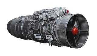
Klimov RD-33 which powers the Mikoyan MiG-29 and Mikoyan MiG-35 fighters
-
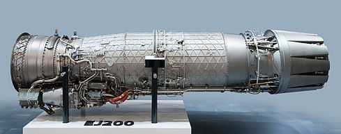
Eurojet EJ200 which powers the Eurofighter Typhoon
-

GTRE GTX-35VS Kaveri developed by GTRE for HAL Tejas
Extreme bypass jet engines
In the 1970s, Rolls-Royce/SNECMA tested a M45SD-02 turbofan fitted with variable pitch fan blades to improve handling at ultra low fan pressure ratios and to provide thrust reverse down to zero aircraft speed. The engine was aimed at ultra quiet STOL aircraft operating from city centre airports.
In a bid for increased efficiency with speed, a development of the turbofan and turboprop known as a propfan engine was created that had an unducted fan. The fan blades are situated outside of the duct, so that it appears like a turboprop with wide scimitar-like blades. Both General Electric and Pratt & Whitney/Allison demonstrated propfan engines in the 1980s. Excessive cabin noise and relatively cheap jet fuel prevented the engines being put into service.
Terminology
- Afterburner
- extra combustor immediately upstream of final nozzle (also called reheat)
- Augmentor
- afterburner on low-bypass turbofan engines.
- Average stage loading
- constant × (delta temperature)/[(blade speed) × (blade speed) × (number of stages)]
- Bypass
- airstream that completely bypasses the core compression system, combustor and turbine system
- Bypass ratio
- bypass airflow /core compression inlet airflow
- Core
- turbomachinery handling the airstream that passes through the combustor.
- Core power
- residual shaft power from ideal turbine expansion to ambient pressure after deducting core compression power
- Core thermal efficiency
- core power/power equivalent of fuel flow
- Dry
- afterburner (if fitted) not lit
- EGT
- Exhaust Gas Temperature
- EPR
- Engine Pressure Ratio
- Fan
- turbofan LP compressor
- Fan pressure ratio
- fan outlet total pressure/intake delivery total pressure
- Flex temp
- use of artificially high apparent air temperature to reduce engine wear
- Gas generator
- engine core
- HP compressor
- high-pressure compressor (also HPC)
- HP turbine
- high-pressure turbine
- Intake ram drag
- penalty associated with jet engines picking up air from the atmosphere (conventional rocket motors do not have this drag term, because the oxidiser travels with the vehicle)
- IEPR
- Integrated engine pressure ratio
- IP compressor
- intermediate pressure compressor (also IPC)
- IP turbine
- intermediate pressure turbine (also IPT)
- LP compressor
- low-pressure compressor (also LPC)
- LP turbine
- low-pressure turbine (also LPT)
- Net thrust
- nozzle total gross thrust - intake ram drag (excluding nacelle drag, etc., this is the basic thrust acting on the airframe)
- Overall pressure ratio
- combustor inlet total pressure/intake delivery total pressure
- Overall thermal efficiency
- thermal efficiency * propulsive efficiency
- Propulsive efficiency
- propulsive power/rate of production of propulsive kinetic energy (maximum propulsive efficiency occurs when jet velocity equals flight velocity, which implies zero net thrust!)
- Specific fuel consumption (SFC)
- total fuel flow/net thrust (proportional to flight velocity/overall thermal efficiency)
- Spooling up
- accelerating, marked by a delay
- Static pressure
- normal meaning of pressure. Excludes any kinetic energy effects
- Specific thrust
- net thrust/intake airflow
- Thermal efficiency
- rate of production of propulsive kinetic energy/fuel power
- Total fuel flow
- combustor (plus any afterburner) fuel flow rate (e.g., lb/s or g/s)
- Total pressure
- static pressure plus kinetic energy term
- Turbine rotor inlet temperature
- gas absolute mean temperature at principal (e.g., HP) turbine rotor entry
See also
- Jet engine
- Turbojet
- Turboprop
- Turboshaft
- Propfan
- Axial fan design
- Variable cycle engine
- Jet engine performance
- Gas turbine
- Turbine engine failure
Notes and references
- ↑ Marshall Brain. "How Gas Turbine Engines Work". howstuffworks.com. Retrieved 2010-11-24.
- ↑ "Turbofan Engine". www.grc.nasa.gov. Retrieved 2010-11-24.
- ↑ 3.0 3.1 Neumann, Gerhard (2004) [1984], Herman the German: Just Lucky I Guess, Bloomington, IN, USA: Authorhouse, ISBN 1-4184-7925-X. First published by Morrow in 1984 as Herman the German: Enemy Alien U.S. Army Master Sergeant. Republished with a new title in 2004 by Authorhouse, with minor or no changes., pp. 228–230.
- ↑ "Metrovick F3 Cutaway - Pictures & Photos on FlightGlobal Airspace". Flightglobal.com. 2007-11-07. Retrieved 2013-04-29.
- ↑ "1954 | 0985 | Flight Archive". Flightglobal.com. 1954-04-09. Retrieved 2013-04-29.
- ↑ RB211-535E4
- ↑ "The geared turbofan technology - Opportunities, challenges and readiness status" PDF C. Riegler, C. Bichlmaier:, 1st CEAS European Air and Space Conference, 10–13 September 2007, Berlin, Germany
- ↑ Kempton, A, "Acoustic liners for modern aero-engines", 15th CEAS-ASC Workshop and 1st Scientific Workshop of X-Noise EV, 2011.
- ↑ A. McAlpine "Research project: Buzz-saw noise and nonlinear acoustics"
- ↑ Schuster, B., Lieber, L., & Vavalle, A., Optimization of a seamless inlet liner using an empirically validated prediction method. In 16th AIAA/CEAS Aeroacoustics Conference, Stockholm, Sweden.
- ↑ Ferrante, P. G., Copiello, D., & Beutke, M.. Design and experimental verification of “true zero-splice” acoustic liners in the universal fan facility adaptation (UFFA) modular rig,”. In 17h AIAA/CEAS Aeroacoustics Conference, AIAA-2011-2728, Portland, OR.
- ↑ Spittle, Peter. "Gas turbine technology" Rolls-Royce plc, 2003. Retrieved: 21 July 2012.
- ↑ About Us | Engine Alliance
- ↑ "International Aero Engines - History". IAE.
- ↑ Slaton, Hunter R., "Vault Guide to the Top Manuafacturing Employers", Vault Inc. (2nd Edition)
- ↑ FlightGlobal. "Honeywell gives AS907 turbofan redesignation." January 13, 2004. Retrieved March 5, 2012.
- ↑ Flight International 13 January 2004
- ↑ By Ernst-Heinrich Hirschel, Horst Prem and Gero Madelung. Published by Springer. "Aeronautical research in Germany: from Lilienthal until today, Volume 147." Page 427.
- ↑ PS-90A turbofan, Aviadvigatel, 2011-01-17
- ↑ Turbofan Engine Family for Regional Jet, Aviadvigatel, 2011-01-17
- ↑ "Eurojet: Company profile". www.eurojet.de. Retrieved 2007-07-05.
External links
| Wikimedia Commons has media related to Turbofan engines. |
| ||||||||||||||||||||||||||||||||||||||||||
| ||||||||||||||||||||||