Transconductance
Transconductance is a property of certain electronic components. Conductance is the reciprocal of resistance; transconductance is the ratio of the current variation at the output to the voltage variation at the input. It is written as gm. For direct current, transconductance is defined as follows:

For small signal alternating current, the definition is simpler:

Terminology
Transconductance is a contraction of transfer conductance. The old unit of conductance, the mho (ohm spelled backwards), was replaced by the SI unit, the siemens, with the symbol S (1 siemens = 1 ampere per volt).
Transresistance
Transresistance, infrequently referred to as mutual resistance, is the dual of transconductance. The term is a contraction of transfer resistance. It refers to the ratio between a change of the voltage at two output points and a related change of current through two input points, and is notated as rm:

The SI unit for transresistance is simply the ohm, as in resistance.
Devices
Vacuum tubes
For vacuum tubes, transconductance is defined as the change in the plate(anode)/cathode current divided by the corresponding change in the grid/cathode voltage, with a constant plate(anode)/cathode voltage. Typical values of gm for a small-signal vacuum tube are 1 to 10 millisiemens. It is one of the three 'constants' of a vacuum tube, the other two being its gain μ and plate resistance rp or ra. The Van der Bijl equation defines their relation as follows:

Field effect transistors
Similarly, in field effect transistors, and MOSFETs in particular, transconductance is the change in the drain current divided by the small change in the gate/source voltage with a constant drain/source voltage. Typical values of gm for a small-signal field effect transistor are 1 to 30 millisiemens.
Using the Shichman–Hodges model, the transconductance for the MOSFET can be expressed as (see MOSFET article):

where ID is the DC drain current at the bias point, and Veff is the effective voltage, which is the difference between the bias point gate–source voltage and the threshold voltage (i.e., Veff := VGS - Vth).[2]:p. 395, Eq. (5.45) The effective voltage (otherwise known as the overdrive voltage) is customarily chosen at about 70–200 mV for the 65 nm technology node (ID ≈ 1.13 mA/μm of width) for a gm of 11–32 mS/μm.[3]:p. 300, Table 9.2[4]:p. 15, §0127
Additionally, the transconductance for the junction FET is given by
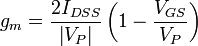 , where VP is the pinchoff voltage and IDSS is the maximum drain current.
Traditionally, the transconductance for the FET and MOSFET as given in the equations above is derived from the transfer equation of each device, using calculus. However, Cartwright[5] has shown that this can be done without calculus.
In datasheets, the transconductance is often called transfer admittance.[6]
Bipolar transistors
The gm of bipolar small-signal transistors varies widely, being proportional to the collector current. It has a typical range of 1 to 400 millisiemens. The input voltage change is applied between the base/emitter and the output is the change in collector current flowing between the collector/emitter with a constant collector/emitter voltage.
The transconductance for the bipolar transistor can be expressed as

where IC = DC collector current at the Q-point, and VT = thermal voltage, typically about 26 mV at room temperature. For a typical current of 10 mA, gm ≈ 385 mS.
Amplifiers
Transconductance amplifiers
A transconductance amplifier (gm amplifier) puts out a current proportional to its input voltage. In network analysis, the transconductance amplifier is defined as a voltage controlled current source (VCCS) . It is common to see these amplifiers installed in a cascode configuration, which improves the frequency response.
Transresistance amplifiers
A transresistance amplifier outputs a voltage proportional to its input current. The transresistance amplifier is often referred to as a transimpedance amplifier, especially by semiconductor manufacturers.
The term for a transresistance amplifier in network analysis is current controlled voltage source (CCVS) .
A basic inverting transresistance amplifier can be built from an operational amplifier and a single resistor. Simply connect the resistor between the output and the inverting input of the operational amplifier and connect the non-inverting input to ground. The output voltage will then be proportional to the input current at the inverting input, decreasing with increasing input current and vice versa. In practice, the parasitic capacitance of whatever device is connected to the virtual ground of the opamp may destabilize it, and a compensating capacitance must be added in parallel with the resistor between the output and inverting pins. Arriving at the optimal value of this compensating capacitor can be non-trivial.
Specialist chip transresistance (transimpedance) amplifiers are widely used for amplifying the signal current from photo diodes at the receiving end of ultra high speed fibre optic links. The MAX3724 and MAX3725 are examples.
Operational transconductance amplifiers
An operational transconductance amplifier (OTA) is an integrated circuit which can function as a transconductance amplifier. These normally have an input to allow the transconductance to be controlled.
See also
- Transistor
- Vacuum tube
- Electronic amplifier
- Transimpedance amplifier
- Fontana bridge
- Operational transconductance amplifier
- MOSFET
References
- ↑ Blencowe, Merlin (2009). "Designing Tube Amplifiers for Guitar and Bass".
- ↑ Sedra, A.S.; Smith, K.C. (1998), Microelectronic Circuits (Fourth ed.), New York: Oxford University Press, ISBN 0-19-511663-1
- ↑ Baker, R. Jacob (2010), CMOS Circuit Design, Layout, and Simulation, Third Edition, New York: Wiley-IEEE, ISBN 978-0-470-88132-3
- ↑ Sansen, W.M.C. (2006), Analog Design Essentials, Dordrecht: Springer, ISBN 0-387-25746-2
- ↑ Cartwright, Kenneth V (Fall 2009), "Derivation of the Exact Transconductance of a FET without Calculus", The Technology Interface Journal 10 (1): 7 pages
- ↑ http://www.ius.edu.ba/sselman/EE301/CH9.pdf
- Horowitz, Paul & Hill, Winfield (1989), The Art of Electronics, Cambridge University Press, ISBN 0-521-37095-7
External links
| Look up transconductance in Wiktionary, the free dictionary. |
- Transconductance — SearchSMB.com Definitions
- Transconductance in audio amplifiers: article by David Wright of Pure Music