Tokamak
.jpg)
A tokamak (Russian: токамак) is a device using a magnetic field to confine a plasma in the shape of a torus. Achieving a stable plasma equilibrium requires magnetic field lines that move around the torus in a helical shape. Such a helical field can be generated by adding a toroidal field (traveling around the torus in circles) and a poloidal field (traveling in circles orthogonal to the toroidal field). In a tokamak, the toroidal field is produced by electromagnets that surround the torus, and the poloidal field is the result of a toroidal electric current that flows inside the plasma. This current is induced inside the plasma with a second set of electromagnets.
The tokamak is one of several types of magnetic confinement devices, and is one of the most-researched candidates for producing controlled thermonuclear fusion power. Magnetic fields are used for confinement since no solid material could withstand the extremely high temperature of the plasma. An alternative to the tokamak is the stellarator.
Tokamaks were invented in the 1950s by Soviet physicists Igor Tamm and Andrei Sakharov, inspired by an original idea of Oleg Lavrentiev.[1]
Etymology
The word tokamak is a transliteration of the Russian word токамак, an acronym of either:
- "тороидальная камера с магнитными катушками" (toroidal'naya kamera s magnitnymi katushkami) — toroidal chamber with magnetic coils (which can also be abbreviated in English as "tochamac");
or
- "тороидальная камера с аксиальным магнитным полем" (toroidal'naya kamera s aksial'nym magnitnym polem) — toroidal chamber with axial magnetic field.[2]
History
Although nuclear fusion research began soon after World War II, the programs in various countries were each initially classified as secret. It was not until after the 1955 United Nations International Conference on the Peaceful Uses of Atomic Energy in Geneva that programs were declassified and international scientific collaboration could take place.
Experimental research of tokamak systems started in 1956 in Kurchatov Institute, Moscow by a group of Soviet scientists led by Lev Artsimovich. The group constructed the first tokamaks, the most successful being T-3 and its larger version T-4. T-4 was tested in 1968 in Novosibirsk, conducting the first ever quasistationary thermonuclear fusion reaction.[3]
In 1968, at the third IAEA International Conference on Plasma Physics and Controlled Nuclear Fusion Research at Novosibirsk, Soviet scientists announced that they had achieved electron temperatures of over 1000 eV in a tokamak device. British and American scientists met this news with skepticism, since they were far from reaching that benchmark; they remained suspicious until laser scattering tests confirmed the findings the next year.
Toroidal design

Positively and negatively charged ions and negatively charged electrons in a fusion plasma are at very high temperatures, and have correspondingly large velocities. In order to maintain the fusion process, particles from the hot plasma must be confined in the central region, or the plasma will rapidly cool. Magnetic confinement fusion devices exploit the fact that charged particles in a magnetic field experience a Lorentz force and follow helical paths along the field lines.
Early fusion research devices were variants on the Z-pinch and used electrical current to generate a poloidal magnetic field to contain the plasma along a linear axis between two points. Researchers discovered that a simple toroidal field, in which the magnetic field lines run in circles around an axis of symmetry, confines a plasma hardly better than no field at all. This can be understood by looking at the orbits of individual particles. The particles not only spiral around the field lines, they also drift across the field. Since a toroidal field is curved and decreases in strength moving away from the axis of rotation, the ions and the electrons move parallel to the axis, but in opposite directions. The charge separation leads to an electric field and an additional drift, in this case outward (away from the axis of rotation) for both ions and electrons. Alternatively, the plasma can be viewed as a torus of fluid with a magnetic field frozen in. The plasma pressure results in a force that tends to expand the torus. The magnetic field outside the plasma cannot prevent this expansion. The plasma simply slips between the field lines.
For a toroidal plasma to be effectively confined by a magnetic field, there must be a twist to the field lines. There are then no longer flux tubes that simply encircle the axis, but, if there is sufficient symmetry in the twist, flux surfaces. Some of the plasma in a flux surface will be on the outside (larger major radius, or "low-field side") of the torus and will drift to other flux surfaces farther from the circular axis of the torus. Other portions of the plasma in the flux surface will be on the inside (smaller major radius, or "high-field side"). Since some of the outward drift is compensated by an inward drift on the same flux surface, there is a macroscopic equilibrium with much improved confinement. Another way to look at the effect of twisting the field lines is that the electric field between the top and the bottom of the torus, which tends to cause the outward drift, is shorted out because there are now field lines connecting the top to the bottom.
When the problem is considered even more closely, the need for a vertical (parallel to the axis of rotation) component of the magnetic field arises. The Lorentz force of the toroidal plasma current in the vertical field provides the inward force that holds the plasma torus in equilibrium.
This device where a large toroidal current is established (15 megaamperes in ITER) suffers from a fundamental problem of stability. The nonlinear evolution of magnetohydrodynamical instabilities leads to a dramatic quench of the plasma current on a very short time scale, of the order of the millisecond. Very energetic electrons are created (runaway electrons) and a global loss of confinement is finally obtained. A very high energy is deposited on small areas. This phenomenon is called a major disruption.[4] The occurrence of major disruptions in running tokamaks has always been rather high, of the order of a few percent of the total numbers of the shots. In currently operated tokamaks, the damage is often large but rarely dramatic. In the ITER tokamak, it is expected that the occurrence of a limited number of major disruptions will definitively damage the chamber with no possibility to restore the device.[5][6][7]
Plasma heating
In an operating fusion reactor, part of the energy generated will serve to maintain the plasma temperature as fresh deuterium and tritium are introduced. However, in the startup of a reactor, either initially or after a temporary shutdown, the plasma will have to be heated to its operating temperature of greater than 10 keV (over 100 million degrees Celsius). In current tokamak (and other) magnetic fusion experiments, insufficient fusion energy is produced to maintain the plasma temperature.
Ohmic heating
Since the plasma is an electrical conductor, it is possible to heat the plasma by inducing a current through it; in fact, the induced current that heats the plasma usually provides most of the poloidal field. The current is induced by slowly increasing the current through an electromagnetic winding linked with the plasma torus: the plasma can be viewed as the secondary winding of a transformer. This is inherently a pulsed process because there is a limit to the current through the primary (there are also other limitations on long pulses). Tokamaks must therefore either operate for short periods or rely on other means of heating and current drive. The heating caused by the induced current is called ohmic (or resistive) heating; it is the same kind of heating that occurs in an electric light bulb or in an electric heater. The heat generated depends on the resistance of the plasma and the amount of electric current running through it. But as the temperature of heated plasma rises, the resistance decreases and ohmic heating becomes less effective. It appears that the maximum plasma temperature attainable by ohmic heating in a tokamak is 20-30 million degrees Celsius. To obtain still higher temperatures, additional heating methods must be used.
Neutral-beam injection
Neutral-beam injection involves the introduction of high-energy (rapidly moving) atoms into the ohmically heated, magnetically confined plasma. The atoms are ionized as they pass through the plasma and are trapped by the magnetic field. The high-energy ions then transfer part of their energy to the plasma particles in repeated collisions, increasing the plasma temperature.
Magnetic compression
A gas can be heated by sudden compression. In the same way, the temperature of a plasma is increased if it is compressed rapidly by increasing the confining magnetic field. In a tokamak system this compression is achieved simply by moving the plasma into a region of higher magnetic field (i.e., radially inward). Since plasma compression brings the ions closer together, the process has the additional benefit of facilitating attainment of the required density for a fusion reactor.

Radio-frequency heating
High-frequency electromagnetic waves are generated by oscillators (often by gyrotrons or klystrons) outside the torus. If the waves have the correct frequency (or wavelength) and polarization, their energy can be transferred to the charged particles in the plasma, which in turn collide with other plasma particles, thus increasing the temperature of the bulk plasma. Various techniques exist including electron cyclotron resonance heating (ECRH) and ion cyclotron resonance heating. This energy is usually transferred by microwaves.
Tokamak cooling
The fusion reactions in the plasma spiraling around a tokamak reactor produce large amounts of high energy neutrons. These neutrons, being electrically neutral, are no longer held in the stream of plasma by the toroidal magnets and continue until stopped by the inside wall of the tokamak. This is a large advantage of tokamak reactors since these freed neutrons provide a simple way to extract heat from the plasma stream; this is how the fusion reactor generates usable energy. The inside wall of the tokamak must be cooled because these neutrons yield enough energy to melt the walls of the reactor. A cryogenic system is used to prevent heat loss from the superconducting magnets. Mostly liquid helium and liquid nitrogen are used as refrigerants.[8] Ceramic plates specifically designed to withstand high temperatures are also placed on the inside reactor wall to protect the magnets and reactor.
Experimental tokamaks
Currently in operation
(in chronological order of start of operations)

- 1960s: TM1-MH (since 1977 Castor; since 2007 Golem[9]) in Prague, Czech Republic. In operation in Kurchatov Institute since early 1960s but renamed to Castor in 1977 and moved to IPP CAS,[10] Prague; in 2007 moved to FNSPE, Czech Technical University in Prague and renamed to Golem.[11]
- 1975: T-10, in Kurchatov Institute, Moscow, Russia (formerly Soviet Union); 2 MW
- 1983: Joint European Torus (JET), in Culham, United Kingdom
- 1983: Novillo Tokamak,[12] at the Instituto Nacional de Investigaciones Nucleares,in Mexico City, Mexico
- 1985: JT-60, in Naka, Ibaraki Prefecture, Japan; (Currently undergoing upgrade to Super, Advanced model)
- 1987: STOR-M, University of Saskatchewan; Canada; first demonstration of alternating current in a tokamak.
- 1988: Tore Supra,[13] at the CEA, Cadarache, France
- 1989: Aditya, at Institute for Plasma Research (IPR) in Gujarat, India
- 1980s: DIII-D,[14] in San Diego, USA; operated by General Atomics since the late 1980s
- 1989: COMPASS,[10] in Prague, Czech Republic; in operation since 2008, previously operated from 1989 to 1999 in Culham, United Kingdom
- 1990: FTU, in Frascati, Italy
- 1991: Tokamak ISTTOK,[15] at the Instituto de Plasmas e Fusão Nuclear, Lisbon, Portugal;
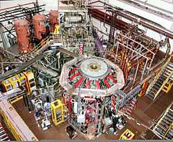 Outside view of the NSTX reactor
 - 1991: ASDEX Upgrade, in Garching, Germany
- 1992: H-1NF (H-1 National Plasma Fusion Research Facility)[16] based on the H-1 Heliac device built by Australia National University's plasma physics group and in operation since 1992
- 1992: Alcator C-Mod,[17] MIT, Cambridge, USA
- 1992: Tokamak à configuration variable (TCV), at the EPFL, Switzerland
- 1994: TCABR, at the University of São Paulo, São Paulo, Brazil; this tokamak was transferred from Centre des Recherches en Physique des Plasmas in Switzerland
- 1995: HT-7, in Hefei, China
- 1999: MAST, in Culham, United Kingdom
- 1999: NSTX in Princeton, New Jersey
- 1999: Globus-M in Ioffe Institute, Saint Petersburg, Russia
- 1990s: Pegasus Toroidal Experiment[18] at the University of Wisconsin-Madison; in operation since the late 1990s
- 2002: HL-2A, in Chengdu, China
- 2006: EAST (HT-7U), in Hefei, China (ITER member)
- 2008: KSTAR, in Daejon, South Korea (ITER member)
- 2010: JT-60SA, in Naka, Japan (ITER member); upgraded from the JT-60.
- 2012: SST-1, in Gandhinagar, India (ITER member); the Institute for Plasma Research reports 1000 seconds operation.[19]
- 2012: IR-T1, Islamic Azad University, Science and Research Branch, Tehran, Iran[20]
- 2012: ST25 at Tokamak Energy at Culham, Oxfordshire, UK (now at Milton Park)[21]
- 2014: ST25 (HTS) the first tokamak to have all magnetic fields formed from high temperature superconducting magnets, at Tokamak Energy based in Oxfordshire, UK[21]
Previously operated

- 1960s: T-3 and T-4, in Kurchatov Institute, Moscow, Russia (formerly Soviet Union); T-4 in operation in 1968.
- 1963: LT-1, Australia National University's plasma physics group built the first tokamak outside of Soviet Union c. 1963
- 1971-1980: Texas Turbulent Tokamak, University of Texas at Austin, USA
- 1973-1976: Tokamak de Fontenay aux Roses (TFR), near Paris, France
- 1973-1979: Alcator A, MIT, USA
- 1978-1987: Alcator C, MIT, USA
- 1978-2013: TEXTOR, in Jülich, Germany
- 1979-1998: MT-1 Tokamak, Budapest, Hungary (Built at the Kurchatov Institute, Russia, transported to Hungary in 1979, rebuilt as MT-1M in 1991)
- 1980-2004: TEXT/TEXT-U, University of Texas at Austin, USA
- 1982-1997: TFTR, Princeton University, USA
- 1987-1999: Tokamak de Varennes; Varennes, Canada; operated by Hydro-Québec and used by researchers from Institut de recherche en électricité du Québec (IREQ) and the Institut national de la recherche scientifique (INRS)
- 1988-2005: T-15, in Kurchatov Institute, Moscow, Russia (formerly Soviet Union); 10 MW
- 1991-1998: START in Culham, United Kingdom
- 1990s-2001: COMPASS, in Culham, United Kingdom
- 1994-2001: HL-1M Tokamak, in Chengdu, China
- 1999-2005: UCLA Electric Tokamak, in Los Angeles, USA
Planned
- ITER, international project in Cadarache, France; 500 MW; construction began in 2010, first plasma expected in 2020.[22]
- DEMO; 2000 MW, continuous operation, connected to power grid. Planned successor to ITER; construction to begin in 2024 according to preliminary timetable.
See also
- Magnetic mirrors
- Edge-Localized Mode
- Stellarator
- Reversed-field pinch
- List of plasma (physics) articles
- The section on Dimensionless parameters in tokamaks in the article on Plasma scaling
Notes
- ↑ Bondarenko B D "Role played by O. A. Lavrent'ev in the formulation of the problem and the initiation of research into controlled nuclear fusion in the USSR" Phys. Usp. 44 844 (2001) available online
- ↑ Merriam-Webster Online
- ↑ Great Soviet Encyclopedia, 3rd edition, entry on "Токамак", available online here
- ↑ Kruger, S. E.; Schnack, D. D.; Sovinec, C. R., (2005). "Dynamics of the Major Disruption of a DIII-D Plasma". Phys. Plasmas 12, 056113. doi:10.1063/1.1873872. <http://www.scidac.gov/FES/FES_FusionGrid/pubs/kruger-phys-plasma-2005.pdf
- ↑ Wurden, G., (2011) International Workshop "MFE Roadmapping in the ITER Era", Princeton <http://advprojects.pppl.gov/Roadmapping/presentations/MFE_POSTERS/WURDEN_Disruption_RiskPOSTER.pdf>
- ↑ Baylor, L. R.; Combs, S. K.; Foust, C. R.; Jernigan, T.C.; Meitner, S. J.; Parks, P. B.; Caughman, J. B.; Fehling, D. T.; Maruyama, S.; Qualls, A. L.; Rasmussen, D. A.; Thomas, C. E., (2009). "Pellet Fuelling, ELM Pacing and Disruption Mitigation Technology Development for ITER". Nucl. Fusion 49 085013. doi:10.1088/0029-5515/49/8/085013. <http://www-pub.iaea.org/MTCD/Meetings/FEC2008/it_p6-19.pdf>
- ↑ Thornton, A. J.; Gibsonb, K. J.; Harrisona, J. R.; Kirka, A.; Lisgoc, S. W.; Lehnend, M.; Martina, R.;, Naylora, G.; Scannella, R.; Cullena, A. and MAST Team Thornton, A.,(2011). "Disruption mitigation studies on the Mega Amp Spherical Tokamak (MAST)". Journal Nucl. Mat. 415, 1, Supplement, 1, S836-S840. doi:10.1016/j.jnucmat.2010.10.029.
- ↑ Tokamak Cryogenics reference
- ↑ Golem tokamak
- ↑ 10.0 10.1 Institute of Plasma Physics, Czech Academy of Science
- ↑ History of Golem
- ↑ Ramos J., Meléndez L. et al., Diseño del Tokamak Novillo, Rev. Mex. Fís. 29 (4), 551, 1983
- ↑ Tore Supra
- ↑ DIII-D (video)
- ↑ ISTTOK
- ↑ http://h1nf.anu.edu.au/media/pdfs/Blackwell_AIP_fusion_article_draft_6-1.pdf
- ↑ Alcator C-Mod
- ↑ Pegasus Toroidal Experiment
- ↑ The SST-1 Tokamak Page
- ↑ "Tokamak". Pprc.srbiau.ac.ir. Retrieved 2012-06-28.
- ↑ 21.0 21.1 http://www.tokamakenergy.co.uk/about-us/
- ↑ "ITER & Beyond. The Phases of ITER.". Retrieved 12 September 2012.
References
- Braams, C.M., Stott, P.E. (2002). Nuclear Fusion: Half a Century of Magnetic Confinement Research. Institute of Physics Publishing. ISBN 0-7503-0705-6.
- Dolan, Thomas J. (1982). Fusion Research, Volume 1 - Principles. Pergamon Press. LCC QC791.D64.
- Nishikawa, K., Wakatani, M. (2000). Plasma Physics. Springer-Verlag. ISBN 3-540-65285-X.
- Raeder, J. et al. (1986). Controlled Nuclear Fusion. John Wiley & Sons. ISBN 0-471-10312-8.
- Wesson, John (2000). The Science of JET (PDF).
- Wesson, John et al. (2004). Tokamaks. Oxford University Press. ISBN 0-19-850922-7.
External links
| Wikimedia Commons has media related to Tokamaks. |
- CCFE - site from the UK fusion research centre CCFE.
- Plasma Science - site on tokamaks from the French CEA.
- Fusion Programs at General Atomics, including the DIII-D National Fusion Facility, an experimental tokamak.
- General Atomics DIII-D Program
- Fusion and Plasma Physics Seminar at MIT OCW
- Unofficial ITER fan club, Club for fans of the biggest tokamak planned to be built in near future.
- www.tokamak.info Extensive list of current and historic tokamaks from around the world.
- SSTC-1 Overview video of a small scale tokamak concept.
- SSTC-2 on YouTube Section View Video of a small scale tokamak concept.
- SSTC-3 on YouTube Fly Through Video of a small scale tokamak concept.
- LAP_Tokamak_Development Information on conditions necessary for nuclear reaction in a tokamak reactor
- A. P. Frass (1973). "Engineering Problems In The Design Of Controlled Thermonuclear Reactors" (PDF). Oak Ridge National Laboratory. Retrieved September 2013.
- Observer Newspaper Article on Tokomak Nuclear fusion and the promise of a brighter tomorrow
| ||||||||||||||||||||||||||||
| ||||||||||||||||||||||
| ||||||||||||||||||||||||||||||||||||||||||||||||||||||||||||||||||||