Three-phase electric power

Three-phase electric power is a common method of alternating-current electric power generation, transmission, and distribution.[1] It is a type of polyphase system and is the most common method used by electrical grids worldwide to transfer power. It is also used to power large motors and other heavy loads. A three-phase system is usually more economical than an equivalent single-phase or two-phase system at the same line to ground voltage because it uses less conductor material to transmit electrical power.[2] The three-phase system was independently invented by Galileo Ferraris, Mikhail Dolivo-Dobrovolsky, Jonas Wenström and Nikola Tesla in the late 1880s.
Principle

In a symmetric three-phase power supply system, three conductors each carry an alternating current of the same frequency and voltage relative to a common reference but with a phase difference of one third the period. The common reference is usually connected to ground and often to a current-carrying conductor called the neutral. Due to the phase difference, the voltage on any conductor reaches its peak at one third of a cycle after one of the other conductors and one third of a cycle before the remaining conductor. This phase delay gives constant power transfer to a balanced linear load. It also makes possible to produce a rotating magnetic field in an electric motor and generate other phase arrangements using transformers (For instance, a two phase system using a Scott-T transformer).
The symmetric three‐phase systems described are referred to as just three‐phase systems because although it is possible to design and implement asymmetric three‐phase power systems (those with unequal voltages or phase shift), they are not used in practice because they lack the most important advantages of symmetric systems.
In a three‐phase system feeding a balanced and linear load, the sum of the instantaneous currents of the three conductors is zero. Equivalently, the current in each conductor is equal in magnitude but with the opposite sign as the sum of the currents in the other two. This means that the return path for the current in any phase conductor is the other two phase conductors.
Compared to a single phase AC power supply that uses two conductors (phase and neutral), a three phase supply with no neutral, the same phase to ground voltage and per-phase current capacity can transmit 3 times the power using 1.5 times as many wires (3 compared to 2). This means that ratio of capacity to conductor material is doubled. The same (but not the other properties of three-phase power) can also be attained with a center-grounded single phase system.
Three-phase systems may also utilize a fourth wire, particularly in low-voltage distribution. This is the neutral wire. The neutral allows three separate single-phase supplies to be provided at a constant voltage and is commonly used for supplying groups of domestic properties which are each single-phase loads. The connections are arranged so that, as far as possible in each group, equal power is drawn from each phase. Further up the distribution system, the currents are usually well balanced. Transformers may be wired in a way that they have a four‐wire secondary but a three‐wire primary while allowing unbalanced loads and the associated secondary‐side neutral currents.
Three-phase supplies have properties that make them very desirable in electric power distribution systems:
- The phase currents tend to cancel out one another, summing to zero in the case of a linear balanced load. This makes it possible to reduce the size of the neutral conductor because it carries little or no current. With a balanced load, all the phase conductors carry the same current and so can be the same size.
- Power transfer into a linear balanced load is constant, which helps to reduce generator and motor vibrations.
- Three-phase systems can produce a rotating magnetic field with a specified direction and constant magnitude, which simplifies the design of electric motors.
Most household loads are single-phase. In North American residences, three-phase power might feed a multiple-unit apartment block, but the household loads are connected only as single phase. In lower-density areas, only a single phase might be used for distribution. Some large European appliances may be powered by three-phase power, such as electric stoves and clothes dryers.
Wiring for the three phases is typically identified by color codes which vary by country. Connection of the phases in the right order is required to ensure the intended direction of rotation of three-phase motors. For example, pumps and fans may not work in reverse. Maintaining the identity of phases is required if there is any possibility two sources can be connected at the same time; a direct interconnection between two different phases is a short-circuit.
Generation and distribution

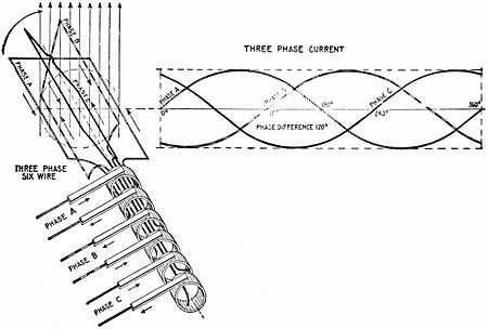
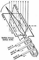
At the power station, an electrical generator converts mechanical power into a set of three AC electric currents, one from each coil (or winding) of the generator. The windings are arranged such that the currents vary sinusoidally at the same frequency but with the peaks and troughs of their wave forms offset to provide three complementary currents with a phase separation of one-third cycle (120° or 2π⁄3 radians). The generator frequency is typically 50 or 60 Hz, varying by country.
At the power station, transformers change the voltage from generators to a level suitable for transmission minimizing losses.
After further voltage conversions in the transmission network, the voltage is finally transformed to the standard utilization before power is supplied to customers.
Most automotive alternators generate three phase AC and rectify it to DC with a diode bridge.[5]
Transformer connections
A "delta" connected transformer winding is connected between phases of a three-phase system. A "wye" ("star") transformer connects each winding from a phase wire to a common neutral point.
In an "open delta" or "V" system, only two transformers are used. A closed delta system can operate as an open delta if one of the transformers has failed or needs to be removed.[6] In open delta, each transformer must carry current for its respective phases as well as current for the third phase, therefore capacity is reduced to 87%. With one of three transformers missing and the remaining two at 87% efficiency, the capacity is 58% ((2/3) × 87%).[7][8]
Where a delta-fed system must be grounded for detection of stray current to ground or protection from surge voltages, a grounding transformer (usually a zigzag transformer) may be connected to allow ground fault currents to return from any phase to ground. Another variation is a "corner grounded" delta system, which is a closed delta that is grounded at one of the junctions of transformers.[9]
Three-wire and four-wire circuits

There are two basic three-phase configurations: delta and wye (star). As shown on the left, a delta configuration requires only 3 wires for transmission but a wye (star) configuration may utilise a fourth wire. The fourth wire, if present, is provided as a Neutral and is normally Grounded. The "3-wire" and "4-wire" designations do not count the ground wire used above many transmission lines, which is solely for fault protection and does not carry current under non-fault conditions.
A four-wire system with symmetrical voltages between phase and neutral is obtained when the neutral is connected to the "common star point" of all supply windings. In such a system, all three phases will have the same magnitude of voltage relative to the Neutral. Other non-symmetrical systems have been used.
The four-wire wye system is used when ground referenced voltages or the flexibility of more voltage selections are required. Faults on one phase to ground will cause a protection event (fuse or breaker open) locally and not involve other phases or other connected equipment. An example of application is local distribution in Europe (and elsewhere), where each customer may be only fed from one phase and the neutral (which is common to the three phases). When a group of customers sharing the neutral draw unequal phase currents, the common neutral wire carries the currents resulting from these imbalances. Electrical engineers try to design the system so the loads are balanced as much as possible within premises where 3-phase power is utilized.[10] These same principles apply to the wide scale distribution of power to individual premises. Hence, every effort is made by supply authorities to distribute all three phases over a large number of premises so that, on average, as nearly as possible a balanced load is seen at the point of supply. For domestic use, some countries such as the UK may supply one phase and neutral at a high current (up to 100A) to one property, while others such as Germany may supply 3 phases and neutral to each customer, but at a lower fuse rating, typically 32 A per phase, and "shuffled" to avoid the effect that more load tends to be put on the first phase.
In North America, a high-leg delta supply is sometimes used, where one winding of a delta connected transformer feeding the load is center-tapped and that center tap is grounded and connected as a Neutral, as shown on the right. This setup produces three different voltages. If the voltage between the center tap (neutral) and each of the two adjacent phases is 120 V (100%), the voltage across any two phases is 240 V (200%), and the neutral to "high leg" voltage is ≈ 208 V (173%).[6]
The reason for providing the delta connected supply is usually to power large motors requiring a rotating field. However, the premises concerned will also require the "normal" North American 120 V supplies, two of which are derived (180 degrees "out of phase") between the "Neutral" and either of the center tapped phase points.
Balanced circuits
In the perfectly balanced case all three lines share equivalent loads. Examining the circuits we can derive relationships between line voltage and current, and load voltage and current for wye and delta connected loads.
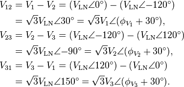
In a balanced system each line will produce equal voltage magnitudes at phase angles equally spaced from each other. With V1 as our reference and V3 lagging V2 lagging V1, using angle notation, we have:[11]


These voltages feed into either a wye or delta connected load.
Wye

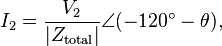
For the wye case, all loads see their respective line voltages, and so:[11]
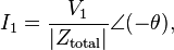
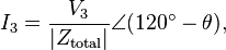
where Ztotal is the sum of line and load impedances (Ztotal = ZLN + ZY), and θ is the phase of the total impedance (Ztotal).
The phase angle difference between voltage and current of each phase is not necessarily 0 and is dependent on the type of load impedance, Zy. Inductive and capacitive loads will cause current to either lag or lead the voltage. However, the relative phase angle between each pair of lines (1 to 2, 2 to 3,and 3 to 1) will still be −120°.
By performing Kirchhoff's current law (KCL) on the neutral node, the three phase currents sum up to the total current in the neutral line. In the balanced case:

Delta
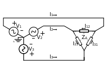
In the delta circuit, loads are connected across the lines, and so loads see line-to-line voltages:[11]
Further:
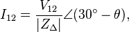
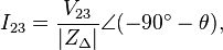
where θ is the phase of delta impedance (ZΔ).
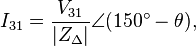
Relative angles are preserved, so I31 lags I23 lags I12 by 120°. Calculating line currents by using KCL at each delta node gives:
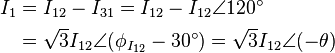
and similarly for each other line:


where, again, θ is the phase of delta impedance (ZΔ).
Single-phase loads
Single-phase loads may be connected across any two phases, or a load can be connected from phase to neutral.[12] Distributing single-phase loads among the phases of a three-phase system balances the load and makes most economical use of conductors and transformers.
In a symmetrical three-phase four-wire, wye system, the three phase conductors have the same voltage to the system neutral. The voltage between line conductors is √3 times the phase conductor to neutral voltage:[13]

The currents returning from the customers' premises to the supply transformer all share the neutral wire. If the loads are evenly distributed on all three phases, the sum of the returning currents in the neutral wire is approximately zero. Any unbalanced phase loading on the secondary side of the transformer will use the transformer capacity inefficiently.
If the supply neutral is broken, phase-to-neutral voltage is no longer maintained. Phases with higher relative loading will experience reduced voltage, and phases with lower relative loading will experience elevated voltage, up to the phase-to-phase voltage.
A high-leg delta provides phase-to-neutral relationship of VLL = 2 VLN , however, LN load is imposed on one phase.[6] A transformer manufacturer's page suggests that LN loading to not exceed 5% of transformer capacity.[14]
Since √3 ≈ 1.73, defining VLN as 100% gives VLL ≈ 100% × 1.73 = 173%. If VLL was set as 100%, then VLN ≈ 57.7%.
Unbalanced loads
When the currents on the three live wires of a three-phase system are not equal or are not at an exact 120° phase angle, the power loss is greater than for a perfectly balanced system. The method of symmetrical components is used to analyze unbalanced systems.
Non-linear loads
With linear loads, the neutral only carries the current due to imbalance between the phases. Devices that utilize rectifier-capacitor front-end such as switch-mode power supplies, computers, office equipment and such produce third-order harmonics that are in-phase on all the supply phases. Consequently, such harmonic currents add in the neutral, which can cause the neutral current to exceed the phase current.[12][15]
Three-phase loads
An important class of three-phase load is the electric motor. A three-phase induction motor has a simple design, inherently high starting torque and high efficiency. Such motors are applied in industry for many applications. A three-phase motor is more compact and less costly than a single-phase motor of the same voltage class and rating and single-phase AC motors above 10 HP (7.5 kW) are uncommon. Three-phase motors also vibrate less and hence last longer than single-phase motors of the same power used under the same conditions.
Line frequency flicker in light can be reduced by evenly spreading three phases across line frequency operated light sources so that illuminated area is provided light from all three phases. The effect of line frequency flicker is detrimental to super slow motion cameras used in sports event broadcasting. Three phase lighting has been applied successfully at the 2008 Beijing Olympics to provide consistent light level for each frame for SSM cameras.[16] Resistance heating loads such as electric boilers or space heating may be connected to three-phase systems. Electric lighting may also be similarly connected.
Rectifiers may use a three-phase source to produce a six-pulse DC output.[17] The output of such rectifiers is much smoother than rectified single phase and, unlike single-phase, does not drop to zero between pulses. Such rectifiers may be used for battery charging, electrolysis processes such as aluminium production or for operation of DC motors. "Zig-zag" transformers may make the equivalent of six-phase full-wave rectification, twelve pulses per cycle, and this method is occasionally employed to reduce the cost of the filtering components, while improving the quality of the resulting DC.
One example of a three-phase load is the electric arc furnace used in steelmaking and in refining of ores.
In many European countries electric stoves are usually designed for a three-phase feed. However, the individual heating units are often connected between phase and neutral to allow for connection to a single-phase circuit e.g. if within an older domestic property a three-phase feed is not yet available.[18] Other usual three-phase loads in the domestic field are tankless water heating systems and storage heater. However since those references appeared homes in Europe and the UK have standardised on a single-phase supply with a nominal 230 v (in practice 240 v in the UK), which is used for all purposes. Most groups of houses are fed from a three-phase supply so that individual premises with above-average demand can be fed with a second or third phase connection, although domestic appliances are invariably designed for a single-phase supply.
Phase converters
Phase converters are used when three-phase equipment needs to be operated on a single-phase power source. They are used when three-phase power is not available or cost is not justifiable. Such converters may also allow the frequency to be varied (resynthesis) allowing speed control. Some railway locomotives use a single-phase source to drive three-phase motors fed through an electronic drive.[19]
Mechanical
One method to generate three-phase power from a single-phase source is the rotary phase converter, essentially a three-phase motor with special starting arrangements and power factor correction that produces balanced three-phase voltages. When properly designed, these rotary converters can allow satisfactory operation of a three-phase motor on a single-phase source. In such a device, the energy storage is performed by the inertia (flywheel effect) of the rotating components. An external flywheel is sometimes found on one or both ends of the shaft.
A three-phase generator can be driven by a single-phase motor. This motor-generator combination can provide a frequency changer function as well as phase conversion, but requires two machines with all their expense and losses. The motor-generator method can also form an uninterruptable power supply when used in conjunction with a large flywheel and a battery-powered DC motor for really constant power, a standby generator set gives more frequency drop until standby generator kicks in.
Non-mechanical
A second method that was popular in the 1940s and 1950s was the transformer method. At that time, capacitors were more expensive than transformers, so an autotransformer was used to apply more power through fewer capacitors. Separated it from another common method, the static converter, as both methods have no moving parts, which separates them from the rotary converters.
Another method often attempted is with a device referred to as a static phase converter. This method of running three-phase equipment is commonly attempted with motor loads though it only supplies 2/3 power and can cause the motor loads to run hot and in some cases overheat. This method does not work when sensitive circuitry is involved such as CNC devices or in induction and rectifier-type loads.
Variable-frequency drives (also known as solid-state inverters and adjustable speed drives) are used to provide precise speed and torque control of three-phase motors. Some models can be powered by a single-phase supply. VFDs work by converting the supply voltage to DC and then converting the DC to a suitable three-phase source for the motor.
Digital phase converters are designed for fixed-frequency operation from a single-phase source. Similar to a variable-frequency drive, they use a microprocessor to control solid-state power switching components to maintain balanced three-phase voltages.
Alternatives to three-phase
- Split-phase electric power is used when three-phase power is not available and allows double the normal utilization voltage to be supplied for high-power loads.
- Two-phase electric power, like three-phase, gives constant power transfer to a linear load. For loads that connect each phase to neutral, assuming the load is the same power draw, the two-wire system has a neutral current that is greater than neutral current in a three-phase system. Also motors are not entirely linear, which means that despite the theory, motors running on three-phase tend to run smoother than those on two-phase. The generators in the Adams Power Plant at Niagara Falls that were installed in 1895 were the largest generators in the world at the time and were two-phase machines. True two-phase power distribution is obsolete for "new work" applications, but still exists for "old work" applications, perhaps most particularly in Buffalo and Niagara Falls, NY, Toronto and Niagara Falls, Ontario, Philadelphia and Reading, PA, and Camden, NJ. "New work" three-phase installations may be supplied by old two-phase feeders, and "old work" two-phase installations may be supplied by new three-phase feeders using a Scott-T transformer, invented by Charles F. Scott.[20] Special-purpose systems may use a two-phase system for frequency control.
- Monocyclic power was a name for an asymmetrical modified two-phase power system used by General Electric around 1897, championed by Charles Proteus Steinmetz and Elihu Thomson. This system was devised to avoid patent infringement. In this system, a generator was wound with a full-voltage single-phase winding intended for lighting loads and with a small fraction (usually 1/4 of the line voltage) winding that produced a voltage in quadrature with the main windings. The intention was to use this "power wire" additional winding to provide starting torque for induction motors, with the main winding providing power for lighting loads. After the expiration of the Westinghouse patents on symmetrical two-phase and three-phase power distribution systems, the monocyclic system fell out of use; it was difficult to analyze and did not last long enough for satisfactory energy metering to be developed.
- High-phase-order systems for power transmission have been built and tested. Such transmission lines typically would use six phases or twelve phases. High-phase-order transmission lines allow transfer of slightly less than proportionately higher power through a given volume without the expense of a high-voltage direct current (HVDC) converter at each end of the line. However, they require correspondingly more pieces of equipment.
Color codes
Conductors of a three-phase system are usually identified by a color code, to allow for balanced loading and to assure the correct phase rotation for motors. Colors used may adhere to International Standard IEC 60446 (now merged into IEC 60445), older standards or to no standard at all and may vary even within a single installation. For example, in the U.S. and Canada, different color codes are used for grounded (earthed) and ungrounded systems.
| Country | L1 | L2 | L3 | Neutral | Ground / protective earth |
|---|---|---|---|---|---|
| Australia and New Zealand as per AS/NZS 3000:2007 Figure 3.2 (or as per IEC 60446 as approved by AS:3000) | Red (or brown) [note 1] | White (or black)[note 1] (prev. yellow) | Dark blue (or grey)[note 1] | Black (or blue)[note 1] | Green/yellow striped (green on very old installations) |
| Canada (mandatory)[21] | Red | Black | Blue | White or Grey | Green or bare copper |
| Canada (isolated three-phase installations)[22] | Orange | Brown | Yellow | White | Green |
| European Union and all countries who use European CENELEC standards April 2004 (IEC 60446), Hong Kong from July 2007, Singapore from March 2009 | Brown | Black | Grey | Blue | Green/yellow striped[note 2] |
| Older European (prior to IEC 60446, varied by country [note 3] | Red | Yellow | Blue | Black | Green/yellow striped (green on installations before c. 1970) |
| UK before April 2006, Hong Kong before April 2009, South Africa, Malaysia, Singapore before February 2011 | Red | Yellow | Blue | Black | Green/yellow striped (green on installations before c. 1970) |
| India | Red | Yellow | Blue | Black | Green/yellow striped, or green |
| Former USSR (Russia, Ukraine, Kazakhstan) and People's Republic of China (per GB 50303-2002 Section 15.2.2) | Yellow | Green | Red | Sky blue | Green/yellow striped |
| Norway | Black | White/Grey | Brown | Blue | Yellow/green striped, older may be only yellow or bare copper |
| United States (common practice)[note 4] | Black | Red | Blue | White, or grey | Green, green/yellow striped,[note 5] or a bare copper wire |
| United States (alternative practice)[note 6] | Brown | Orange (delta systems), or violet (wye systems) | Yellow | Grey, or white | Green |
See also
- Three-phase AC railway electrification
- Charging station
- Frequency converter
- Industrial & multiphase power plugs & sockets
- International Electrotechnical Exhibition
- John Hopkinson
- Y-Δ transform
Notes
- ↑ 1.0 1.1 1.2 1.3 In Australia and New Zealand, active conductors can be any color except green/yellow, green, yellow, black or light blue. Yellow is no longer permitted in the 2007 revision of wiring code ASNZS 3000. European color codes are used for all IEC or flex cables such as extension leads, appliance leads etc. and are equally permitted for use in building wiring per AS/NZS 3000:2007.
- ↑ The international standard green-yellow marking of protective-earth conductors was introduced to reduce the risk of confusion by color blind installers. About 7% to 10% of men cannot clearly distinguish between red and green, which is a particular concern in older schemes where red marks a live conductor and green marks protective earth or safety ground.
- ↑ In Europe, there still exist many installations with older colors but, since the early 1970s, all new installations use green/yellow earth according to IEC 60446. (E.g. Phase/Neutral+Earth German: black/grey + red France green/red + White Russia: Red/ Grey + Black; Switzerland: Red/ Grey +Yellow or yellow & red Denmark: White/Black + Red
- ↑ See Paul Cook: Harmonised colours and alphanumeric marking. IEE Wiring Matters, Spring 2006.
- ↑ In the U.S., a green/yellow striped wire may indicate an isolated ground. In most countries today, green/yellow striped wire may only be used for protective earth (safety ground) and may never be unconnected or used for any other purpose.
- ↑ Since 1975, the U.S. National Electric Code has not specified coloring of phase conductors. It is common practice in many regions to identify 120/208 (wye) conductors as black, red, and blue, and 277/480 (wye or delta) conductors as brown, orange, yellow. In a 120/240 delta system with a 208v high leg, the high leg (typically B phase) is always marked orange, commonly A phase is black and C phase is either red or blue. Local regulations may amend the N.E.C. The U.S. National Electric Code has color requirements for grounded conductors, ground, and grounded-delta 3-phase systems which result in one ungrounded leg having a higher voltage potential to ground than the other two ungrounded legs.
References
- ↑ William D. Stevenson, Jr. Elements of Power System Analysis Third Edition, McGraw-Hill, New York (1975). ISBN 0-07-061285-4, p. 2
- ↑ http://www.allaboutcircuits.com/vol_2/chpt_10/2.html
- ↑ Hawkins Electrical Guide, Theo. Audel and Co., 2nd ed., 1917, vol. 4, Ch. 46: Alternating Currents, p. 1026, fig. 1260.
- ↑ Hawkins Electrical Guide, Theo. Audel and Co., 2nd ed., 1917, vol. 4, Ch. 46: Alternating Currents, p. 1026, fig. 1261.
- ↑ http://www.rle.mit.edu/per/conferencepapers/cpconvergence00p583.pdf
- ↑ 6.0 6.1 6.2 Fowler, Nick (2011). Electrician's Calculations Manual 2nd Edition. McGraw-Hill. pp. 3–5. ISBN 9780071770170.
- ↑ McGraw-Hill (1920). Power 51 (17) http://books.google.com/books?id=u91QAAAAYAAJ&pg=PA673&lpg=PA673. Retrieved 21 December 2012. Missing or empty
|title=(help) - ↑ H. W. Beaty, D.G.Fink (ed) Standard Handbook for Electrical Engineers Fifteenth Edition,McGraw-Hill, 2007 ISBN 0-07-144146-8, p. 10–11
- ↑ Schneider
- ↑ http://www.rapid-tech.com.au/Fluke-2_Saving%20energy%20through%20load%20balancing.pdf
- ↑ 11.0 11.1 11.2 J. Duncan Glover; Mulukutla S. Sarma; Thomas J. Overbye (April 2011). Power System Analysis & Design. Cengage Learning. pp. 60–68. ISBN 978-1-111-42579-1.
- ↑ 12.0 12.1 Lowenstein, Michael. "The 3rd Harmonic Blocking Filter: A Well Established Approach to Harmonic Current Mitigation". IAEI Magazine. Retrieved 24 November 2012.
- ↑ The boy electrician by J W Sims M.I.E.E. (Page 98)
- ↑ Federal pacific
- ↑ Enjeti, Prasad. "Harmonics in Low Voltage Three-Phase Four-Wire Electric Distribution Systems and Filtering Solutions" (PDF). Texas A&M University Power Electronics and Power Quality Laboratory. Retrieved 24 November 2012.
- ↑ Hui, Sun. "Sports Lighting – Design Considerations For The Beijing 2008 Olympic Games" (PDF). GE Lighting. Retrieved 18 December 2012.
- ↑ IEEE
- ↑ "British and European practices for domestic appliances compared", Electrical Times, volume 148, page 691, 1965.
- ↑ Japan Railway & Transport Review (PDF). No. 58: 58. Oct 2011 http://www.jrtr.net/jrtr58/pdf/51-60web.pdf. Missing or empty
|title=(help) - ↑ Brittain, J. E. (2007). "Electrical Engineering Hall of Fame: Charles F. Scott". Proceedings of the IEEE 95 (4): 836–839. doi:10.1109/JPROC.2006.892488.
- ↑ Canadian Electrical Code Part I, 23rd Edition, (2002) ISBN 1-55324-690-X, rule 4-036 (3)
- ↑ Canadian Electrical Code 23th edition 2002, rule 24-208(c)
