Thermistor
| Thermistor | |
|---|---|
|
Negative temperature coefficient (NTC) thermistor, bead type, insulated wires | |
| Type | Passive |
| Working principle | Electric resistance |
| Electronic symbol | |
|
Thermistor symbol | |

A thermistor is a type of resistor whose resistance varies significantly with temperature, more so than in standard resistors. The word is a portmanteau of thermal and resistor. Thermistors are widely used as inrush current limiter, temperature sensors (NTC type typically), self-resetting overcurrent protectors, and self-regulating heating elements.
Thermistors differ from resistance temperature detectors (RTDs) in that the material used in a thermistor is generally a ceramic or polymer, while RTDs use pure metals. The temperature response is also different; RTDs are useful over larger temperature ranges, while thermistors typically achieve a higher precision within a limited temperature range, typically −90 °C to 130 °C.[1]
Basic operation
Assuming, as a first-order approximation, that the relationship between resistance and temperature is linear, then:

where
 , change in resistance
 , change in temperature
 , first-order temperature coefficient of resistance
Thermistors can be classified into two types, depending on the classification of . If is positive, the resistance increases with increasing temperature, and the device is called a positive temperature coefficient (PTC) thermistor, or posistor. If is negative, the resistance decreases with increasing temperature, and the device is called a negative temperature coefficient (NTC) thermistor. Resistors that are not thermistors are designed to have a as close to 0 as possible, so that their resistance remains nearly constant over a wide temperature range.
Instead of the temperature coefficient k, sometimes the temperature coefficient of resistance  (alpha sub T) is used. It is defined as[2]
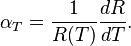
This coefficient should not be confused with the  parameter below.
Steinhart–Hart equation
In practice, the linear approximation (above) works only over a small temperature range. For accurate temperature measurements, the resistance/temperature curve of the device must be described in more detail. The Steinhart–Hart equation is a widely used third-order approximation:
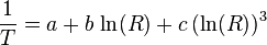
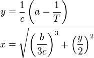
where a, b and c are called the Steinhart–Hart parameters, and must be specified for each device. T is the absolute temperature and R is the resistance. To give resistance as a function of temperature, the above can be rearranged into:
![R = \mathrm{exp} \left[{{\left( x - {1 \over 2}y \right)}^{1 \over 3} - {\left( x + {1 \over 2}y \right)}^{1 \over 3}}\right]](../I/m/1b89e9dcc095c3f5415d8546cd229ea1.png)
where
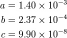
The error in the Steinhart–Hart equation is generally less than 0.02 °C in the measurement of temperature over a 200 °C range.[3] As an example, typical values for a thermistor with a resistance of 3000 Ω at room temperature (25 °C = 298.15 K) are:
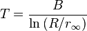
B or β parameter equation
NTC thermistors can also be characterised with the B (or β) parameter equation, which is essentially the Steinhart–Hart equation with  ,
,  and
and  ,
,
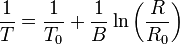
Where the temperatures are in kelvin and R0 is the resistance at temperature T0 (25 °C = 298.15 K). Solving for R yields:
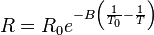
or, alternatively,
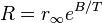
where 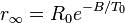 .
.
This can be solved for the temperature:
The B-parameter equation can also be written as 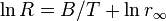 . This can be used to convert the function of resistance vs. temperature of a thermistor into a linear function of
  vs.
vs.  . The average slope of this function will then yield an estimate of the value of the B parameter.
Conduction model
NTC
Many NTC thermistors are made from a pressed disc, rod, plate, bead or cast chip of a semiconductor such as a sintered metal or other oxides that are used in semiconductors. They work because raising the temperature of a semiconductor increases the number of active charge carriers - it promotes them into the conduction band. The more charge carriers that are available, the more current a material can conduct. In certain materials like ferric oxide (Fe2O3) with titanium (Ti) doping a n-type semiconductor is formed and the charge carriers are electrons. In materials such as nickel oxide (NiO) with lithium (Li) doping a p-type semiconductor is created where holes are the charge carriers.[4]
This is described in the formula:

 = electric current (amperes)
 = density of charge carriers (count/m³)
 = cross-sectional area of the material (m²)
 = velocity of charge carriers (m/s)
 = charge of an electron (
 coulomb)
Over large changes in temperature, calibration is necessary. Over small changes in temperature, if the right semiconductor is used, the resistance of the material is linearly proportional to the temperature. There are many different semiconducting thermistors with a range from about 0.01 kelvin to 2,000 kelvins (−273.14 °C to 1,700 °C).
PTC
Most PTC thermistors are of the "switching" type, which means that their resistance rises suddenly at a certain critical temperature. The devices are made of a doped polycrystalline ceramic containing barium titanate (BaTiO3) and other compounds. The dielectric constant of this ferroelectric material varies with temperature. Below the Curie point temperature, the high dielectric constant prevents the formation of potential barriers between the crystal grains, leading to a low resistance. In this region the device has a small negative temperature coefficient. At the Curie point temperature, the dielectric constant drops sufficiently to allow the formation of potential barriers at the grain boundaries, and the resistance increases sharply. At even higher temperatures, the material reverts to NTC behaviour.
Another type of thermistor is a silistor, a thermally sensitive silicon resistor. Silistors employ silicon as the semiconductive component material. In contrary to the "switching" type thermistor, silistors have an almost linear resistance-temperature characteristic.[5]
The degaussing coils in many CRT monitors were controlled by thermistors bonded to a small heating element. The thermistor would be connected in series with the coil across the AC input, with the heater also directly connected to the AC input. When cold the thermistor would allow a large current to flow through but would be quickly heated by the heating element and the current would trail to zero. This would degauss the screen every time the power is removed for long enough for the device to cool.
Another device similar in function to PTC thermistor is the polymer PTC, which is sold under brand names such as "Polyswitch" "Semifuse", and "Multifuse". This consists of a slice of plastic with carbon grains embedded in it. When the plastic is cool, the carbon grains are all in contact with each other, forming a conductive path through the device. When the plastic heats up, it expands, forcing the carbon grains apart, and causing the resistance of the device to rise rapidly. Like the BaTiO3 thermistor, this device has a highly nonlinear resistance/temperature response and is used for switching, not for proportional temperature measurement.
Self-heating effects
When a current flows through a thermistor, it will generate heat which will raise the temperature of the thermistor above that of its environment. If the thermistor is being used to measure the temperature of the environment, this electrical heating may introduce a significant error if a correction is not made. Alternatively, this effect itself can be exploited. It can, for example, make a sensitive air-flow device employed in a sailplane rate-of-climb instrument, the electronic variometer, or serve as a timer for a relay as was formerly done in telephone exchanges.
The electrical power input to the thermistor is just:

where I is current and V is the voltage drop across the thermistor. This power is converted to heat, and this heat energy is transferred to the surrounding environment. The rate of transfer is well described by Newton's law of cooling:

where T(R) is the temperature of the thermistor as a function of its resistance R,  is the temperature of the surroundings, and K is the dissipation constant, usually expressed in units of milliwatts per degree Celsius. At equilibrium, the two rates must be equal.

The current and voltage across the thermistor will depend on the particular circuit configuration. As a simple example, if the voltage across the thermistor is held fixed, then by Ohm's Law we have  and the equilibrium equation can be solved for the ambient temperature as a function of the measured resistance of the thermistor:
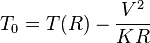
The dissipation constant is a measure of the thermal connection of the thermistor to its surroundings. It is generally given for the thermistor in still air, and in well-stirred oil. Typical values for a small glass bead thermistor are 1.5 mW/°C in still air and 6.0 mW/°C in stirred oil. If the temperature of the environment is known beforehand, then a thermistor may be used to measure the value of the dissipation constant. For example, the thermistor may be used as a flow rate sensor, since the dissipation constant increases with the rate of flow of a fluid past the thermistor.
The power dissipated in a thermistor is typically maintained at a very low level to ensure insignificant temperature measurement error due to self heating. However, some thermistor applications depend upon significant "self heating" to raise the body temperature of the thermistor well above the ambient temperature so the sensor then detects even subtle changes in the thermal conductivity of the environment. Some of these applications include liquid level detection, liquid flow measurement and air flow measurement.[2]
Applications
- PTC thermistors can be used as current-limiting devices for circuit protection, as replacements for fuses. Current through the device causes a small amount of resistive heating. If the current is large enough to generate more heat than the device can lose to its surroundings, the device heats up, causing its resistance to increase. This creates a self-reinforcing effect that drives the resistance upwards, therefore limiting the current.
- PTC thermistors were used as timers in the degaussing coil circuit of most CRT displays. When the display unit is initially switched on, current flows through the thermistor and degaussing coil. The coil and thermistor are intentionally sized so that the current flow will heat the thermistor to the point that the degaussing coil shuts off in under a second. For effective degaussing, it is necessary that the magnitude of the alternating magnetic field produced by the degaussing coil decreases smoothly and continuously, rather than sharply switching off or decreasing in steps; the PTC thermistor accomplishes this naturally as it heats up. A degaussing circuit using a PTC thermistor is simple, reliable (for its simplicity), and inexpensive.
- PTC thermistors were used as heater in automotive industry to provide additional heat inside cabin with diesel engine or to heat diesel in cold climatic conditions before engine injection.
- PTC thermistors are used in temperature compensated synthesizer voltage controlled oscillators.[6]
- NTC thermistors are used as resistance thermometers in low-temperature measurements of the order of 10 K.
- NTC thermistors can be used as inrush-current limiting devices in power supply circuits. They present a higher resistance initially which prevents large currents from flowing at turn-on, and then heat up and become much lower resistance to allow higher current flow during normal operation. These thermistors are usually much larger than measuring type thermistors, and are purposely designed for this application.[7]
- NTC thermistors are regularly used in automotive applications. For example, they monitor things like coolant temperature and/or oil temperature inside the engine and provide data to the ECU and, indirectly, to the dashboard.
- NTC thermistors can be also used to monitor the temperature of an incubator.
- Thermistors are also commonly used in modern digital thermostats and to monitor the temperature of battery packs while charging.
- Thermistors are often used in the hot ends of 3D printers; they monitor the heat produced and allow the printer's control circuitry to keep a constant temperature for melting the plastic filament.
- NTC thermistors are used in the Food Handling and Processing industry, especially for food storage systems and food preparation. Maintaining the correct temperature is critical to prevent food borne illness.
- NTC thermistors are used throughout the Consumer Appliance industry for measuring temperature. Toasters, coffee makers, refrigerators, freezers, hair dryers, etc. all rely on thermistors for proper temperature control.
- NTC thermistors come in bare and lugged forms, the former is for point sensing to achieve high accuracy for specific points, such as laser diode die, etc.[8]
History
The first NTC thermistor was discovered in 1833 by Michael Faraday, who reported on the semiconducting behavior of silver sulfide. Faraday noticed that the resistance of silver sulfide decreased dramatically as temperature increased. (This was also the first documented observation of a semiconducting material.) [9]
Because early thermistors were difficult to produce and applications for the technology were limited, commercial production of thermistors did not begin until the 1930s.[10] A commercially viable thermistor was invented by Samuel Ruben in 1930.[11]
See also
References
- ↑ "NTC Thermistors". Micro-chip Technologies. 2010.
- ↑ 2.0 2.1 Thermistor Terminology. U.S. Sensor
- ↑ "Practical Temperature Measurements". Agilent Application Note. Agilent Semiconductor.
- ↑ L. W Turner, ed. (1976). Electronics Engineer's Reference Book (4 ed.). Butterworths. pp. 6–29 to 6–41. ISBN 0408001682.
- ↑ "PTC Thermistors and Silistors" The Resistor Guide
- ↑ Temperature Compensated VCO
- ↑ Inrush Current Limiting Power Thermistors. U.S. Sensor
- ↑ "PTC Thermistors Guide- "Publish By Analog Electronic Technologies".".
- ↑ "1833 - First Semiconductor Effect is Recorded". Computer History Museum. Retrieved 24 June 2014.
- ↑ McGee, Thomas (1988). "Chapter 9". Principles and Methods of Temperature Measurement. John Wiley & Sons. p. 203.
- ↑ Jones, Deric P., ed. (2009). Biomedical Sensors. Momentum Press. p. 12.
External links
| Wikimedia Commons has media related to Thermistors. |
- The thermistor at bucknell.edu
- Software for thermistor calculation at Sourceforge
- "Thermistors & Thermocouples:Matching the Tool to the Task in Thermal Validation" - Journal of Validation Technology
| ||||||||||||||||||||||||||||||||||