Thermal shock
| ||||||
Thermal shock occurs when a thermal gradient causes different parts of an object to expand by different amounts. This differential expansion can be understood in terms of stress or of strain, equivalently. At some point, this stress can exceed the strength of the material, causing a crack to form. If nothing stops this crack from propagating through the material, it will cause the object's structure to fail.
Failure due to thermal shock can be prevented by;
- Reducing the thermal gradient seen by the object, by
- changing its temperature more slowly
- increasing the material's thermal conductivity
- Reducing the material's coefficient of thermal expansion
- Increasing its strength
- Introducing built-in compressive stress, as for example in tempered glass
- Decreasing its Young's modulus
- Increasing its toughness, by
- crack tip blunting, i.e., plasticity or phase transformation
- crack deflection
Effect on materials
Borosilicate glass is made to withstand thermal shock better than most other glass through a combination of reduced expansion coefficient and greater strength, though fused quartz outperforms it in both these respects. Some glass-ceramic materials (mostly in LAS system[1]) include a controlled proportion of material with a negative expansion coefficient, so that the overall coefficient can be reduced to almost exactly zero over a reasonably wide range of temperatures.
Reinforced carbon-carbon is extremely resistant to thermal shock, due to graphite's extremely high thermal conductivity and low expansion coefficient, the high strength of carbon fiber, and a reasonable ability to deflect cracks within the structure.
To measure thermal shock the impulse excitation technique proved to be a useful tool. It can be used to measure Young's modulus, Shear modulus, Poisson's ratio and damping coefficient in a non destructive way. The same test-piece can be measured after different thermal shock cycles and this way the deterioration in physical properties can be mapped out.
Relative robustness of materials
The robustness of a material to thermal shock, or thermal shock resistance[2] is characterized with the thermal shock parameter:[3]
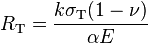 ,
,
where
-
 is thermal conductivity,
 -
 is maximal tension the material can resist,
 -
 is the thermal expansion coefficient
 -
 is the Young's modulus, and
 -
 is the Poisson ratio.
Thermal shock parameter in the physics of solid-state lasers
The laser gain medium generates heat. This heat is drained through the heat sink. The transfer of heat occurs at a certain temperature gradient. The non-uniform thermal expansion of a bulk material causes the stress and tension, which may break the device even at a slow change of temperature. (for example, continuous-wave operation). This phenomenon is also called thermal shock. The robustness of a laser material to the thermal shock is characterized by the thermal shock parameter. [3] (see above)
Roughly, at the efficient operation of laser, the power  of heat generated in the gain medium is proportional to the output power
  of the laser, and the coefficient
  of proportionality can be interpreted as heat generation parameter; then,
  The heat generation parameter is basically determined by the quantum defect of the laser action, and one can estimate
 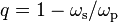 , where
  and
and  are frequency of the pump and that of the lasing.
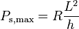
Then, for the layer of the gain medium placed at the heat sink, the maximal power can be estimated as
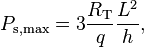
where  is thickness of the layer and
  is the transversal size.
This estimate assumes the unilateral heat drain, as it takes place in the active mirrors.
For the double-side sink, the coefficient 4 should be applied.
is the transversal size.
This estimate assumes the unilateral heat drain, as it takes place in the active mirrors.
For the double-side sink, the coefficient 4 should be applied.
Thermal loading
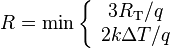
The estimate above is not the only parameter which determines the limit of overheating of a gain medium.
The maximal raise  of temperature, at which the medium still can efficiently lase, is also important property of the laser material.
This overheating limits the maximal power with estimate
of temperature, at which the medium still can efficiently lase, is also important property of the laser material.
This overheating limits the maximal power with estimate
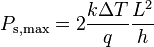
Combination of the two estimates above of the maximal power gives the estimate
where

 , at which desirable output power
  is still available in a single disk laser, versus normalized power
 , and experimental data (circles)
is thermal loading; parameter, which is important property of the laser material. The thermal loading, saturation intensity  and the loss determine the limit of power scaling of the disk lasers
.[5]
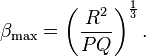
Roughly, the maximal power at the optimised sizes and , is of order of
and the loss determine the limit of power scaling of the disk lasers
.[5]
Roughly, the maximal power at the optimised sizes and , is of order of
 .
This estimate is very sensitive to the loss .
However, the same expression can be interpreted as a robust estimate of the upper bound of the loss
.
This estimate is very sensitive to the loss .
However, the same expression can be interpreted as a robust estimate of the upper bound of the loss  required for the desirable output power :
All the disk lasers reported work at the round-trip loss below this estimate.[4] The thermal shock parameter and the loading depend of the temperature of the heat sink. Certain hopes are related with a laser, operating at cryogenic temperatures. The corresponding Increase of the thermal shock parameter would allow to softer requirements for the round-trip loss of the disk laser at the power scaling.
Thermal Shock Testing
Thermal shock testing exposes products to alternating low and high temperatures to accelerate failures caused by temperature cycles or thermal shocks during normal use.[6] The transition between temperature extremes occurs very rapidly, greater than 15 °C per minute.
Equipment with single or multiple chambers is typically used to perform thermal shock testing. When using single chamber thermal shock equipment, the products remain in one chamber and the chamber air temperature is rapidly cooled and heated. Some equipment uses separate hot and cold chambers with an elevator mechanism that transports the products between two or more chambers.
Examples of thermal shock failure
- Hard rocks containing ore veins such as quartzite were formerly broken down using fire-setting, which involved heating the rock face with a wood fire, then quenching with water to induce crack growth. It is described by Diodorus Siculus in Egyptian gold mines, Pliny the Elder and Georg Agricola.
- Ice cubes placed in a glass of warm water crack by thermal shock as the exterior surface increases in temperature much faster than the interior. As ice has a larger volume than the water that created it, the outer layer shrinks as it warms and begins to melt, whilst the interior remains largely unchanged. This rapid change in volume between different layers creates stresses in the ice that build until the force exceeds the strength of the ice, and a crack forms, sometimes with enough force to shoot ice shards out of the container.
- Incandescent bulbs that have been running for a while have a very hot surface. Splashing cold water on them can cause the glass to shatter due to thermal shock, and the bulb to implode.
- An antique cast iron cookstove is basically an iron box on legs, that has a cast iron top. One builds a wood or coal fire inside the box and cooks on the top outer surface of the box, like a griddle. If one builds too hot a fire, and then tries to cool the stove by pouring water on the top surface, it will crack and perhaps fail by thermal shock.
- The causes of three aircraft incidents in the 1990s (United Airlines Flight 585, USAir Flight 427 and Eastwind Airlines Flight 517). Thermal shock caused their power control unit in the tail to jam and cause rudder hardover, forcing the planes in the direction the rudder turns.
- It is widely hypothesized that following the casting of the Liberty Bell, it was allowed to cool too quickly which weakened the integrity of the bell and resulted in a large crack along the side of it the first time it was rung. Similarly, the strong gradient of temperature (due to the fire) is believed to cause the crash of the Tsar Bell.
- Thermal shock is a primary contributor to head gasket failure in internal combustion engines.
See also
- Strain
- Impulse excitation technique
References
- ↑ Scott L. Swartz, Ceramics having negative coefficient of thermal expansion, method of making such ceramics, and parts made from such ceramics, United States Patent 6066585
- ↑ T. J. Lue; N. A. Fleck (1998). "The Thermal Shock Resistance of Solids" (PDF). Acta Materialia 46 (13): 4755–4768.
- ↑ 3.0 3.1 W.F.Krupke; M.D. Shinn, J.E. Marion, J.A. Caird, and S.E. Stokowski (1986). "Spectroscopic, optical, and thermomechanical properties of neodymium- and chromium-doped gadolinium scandium gallium garnet" (ABSTRACT). JOSAB 3 (1): 102–114. Bibcode:1986JOSAB...3..102K. doi:10.1364/JOSAB.3.000102.
- ↑ 4.0 4.1 D.Kouznetsov; J.-F.Bisson (2008). "Role of the undoped cap in the scaling of a thin disk laser". JOSA B 25 (3): 338–345. Bibcode:2008JOSAB..25..338K. doi:10.1364/JOSAB.25.000338.
- ↑ D. Kouznetsov; J.F. Bisson, J. Dong, and K. Ueda (2006). "Surface loss limit of the power scaling of a thin-disk laser" (ABSTRACT). JOSAB 23 (6): 1074–1082. Bibcode:2006JOSAB..23.1074K. doi:10.1364/JOSAB.23.001074. Retrieved 2007-01-26. ;
- ↑ Delserro Engineering Solutions Blog (29 January 2015). "Thermal Shock Testing – Temperature Cycling". Delserro Engineering Solutions. Retrieved 1 February 2015.