Thermal conductivity measurement
There are a number of possible ways to measure thermal conductivity, each of them suitable for a limited range of materials, depending on the thermal properties and the medium temperature. Two classes of methods exist to measure the thermal conductivity of a sample: steady-state and non-steady-state (or transient) methods.
Steady-state methods
In general, steady-state techniques perform a measurement when the temperature of the material measured does not change with time. This makes the signal analysis straightforward (steady state implies constant signals). The disadvantage is that a well-engineered experimental setup is usually needed.
In geology and geophysics, the most common method for consolidated rock samples is the divided bar. There are various modifications to these devices depending on the temperatures and pressures needed as well as sample sizes. A sample of unknown conductivity is placed between two samples of known conductivity (usually brass plates). The setup is usually vertical with the hot brass plate at the top, the sample in between then the cold brass plate at the bottom. Heat is supplied at the top and made to move downwards to stop any convection within the sample. Measurements are taken after the sample has reached to the steady state (with zero heat gradient or constant heat over entire sample), this usually takes about 30 minutes and over.
Other Steady-state methods
For good conductors of heat, Searle's bar method can be used.[1] For poor conductors of heat, Lees' disc method can be used.[2] according to badjojo
Transient methods
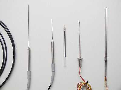
The transient techniques perform a measurement during the process of heating up. The advantage is that measurements can be made relatively quickly. Transient methods are usually carried out by needle probes.
Non-steady-state methods to measure the thermal conductivity do not require the signal to obtain a constant value. Instead, the signal is studied as a function of time. The advantage of these methods is that they can in general be performed more quickly, since there is no need to wait for a steady-state situation. The disadvantage is that the mathematical analysis of the data is in general more difficult.
Transient plane source method
Transient Plane Source Method, utilizing a plane sensor and a special mathematical model describing the heat conductivity, combined with electronics, enables the method to be used to measure Thermal Transport Properties. It covers a thermal conductivity range of at least 0.01-500 W/m/K (in accordance with ISO 22007-2) and can be used for measuring various kinds of materials, such as solids, liquid, paste and thin films etc. In 2008 it was approved as an ISO-standard for measuring thermal transport properties of polymers (November 2008). This TPS standard also covers the use of this method to test both isotropic and anisotropic materials.
The Transient Plane Source technique typically employs two samples halves, in-between which the sensor is sandwiched. Normally the samples should be homogeneous, but extended use of transient plane source testing of heterogeneous material is possible, with proper selection of sensor size to maximize sample penetration. This method can also be used in a single-sided configuration, with the introduction of a known insulation material used as sensor support.
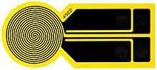
The flat sensor consists of a continuous double spiral of electrically conducting nickel (Ni) metal, etched out of a thin foil. The nickel spiral is situated between two layers of thin polyimide film Kapton. The thin Kapton films provides electrical insulation and mechanical stability to the sensor. The sensor is placed between two halves of the sample to be measured. During the measurement a constant electrical effect is passes through the conducting spiral, increasing the sensor temperature. The heat generated dissipates into the sample on both sides of the sensor, at a rate depending on the thermal transport properties of the material. By recording temperature vs. time response in the sensor, the thermal conductivity, thermal diffusivity and specific heat capacity of the material can be calculated.
Modified transient plane source (MTPS) method
A variation of the above method is the Modified Transient Plane Source Method (MTPS) developed by Dr. Nancy Mathis. The device uses a one-sided, interfacial, heat reflectance sensor that applies a momentary, constant heat source to the sample. The difference between this method and traditional transient plane source technique described above is that the heating element is supported on a backing, which provides mechanical support, electrical insulation and thermal insulation. This modification provides a one-sided interfacial measurement in offering maximum flexibility in testing liquids, powders, pastes and solids.
Transient line source method
The physical model behind this method is the infinite line source with constant power per unit length. The temperature profile  at a distance
  at time
  is as follows
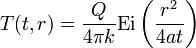
where
-
 is the power per unit length, in [W·m−1]
 -
 is the thermal conductivity of the sample, in [W·m−1·K−1]
 -
 is the exponential integral, a transcendent mathematical function
 - is the radial distance to the line source
-
 is the thermal diffusivity, in [m2·s−1]
 - is the amount of time that has passed since heating has started, in [s]
When performing an experiment, one measures the temperature at a point at fixed distance, and follows that temperature in time. For large times, the exponential integral can be approximated by making use of the following relation

where
-
 is the Euler gamma constant
This leads to the following expression
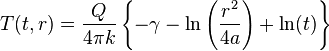
Note that the first two terms in the brackets on the RHS are constants. Thus if the probe temperature is plotted versus the natural logarithm of time, the thermal conductivity can be determined from the slope given knowledge of Q. Typically this means ignoring the first 60 to 120 seconds of data and measuring for 600 to 1200 seconds.
Laser Flash Method
The laser flash method is used to measure thermal diffusivity of a thin disc in the thickness direction. This method is based upon the measurement of the temperature rise at the rear face of the thin-disc specimen produced by a short energy pulse on the front face. With a reference sample specific heat can be achieved and with known density the thermal conductivity results as follows

where
- is the thermal conductivity of the sample, in [W·m−1·K−1]
- is the thermal diffusivity of the sample, in [m2 ·s−1]
-
 is the specific heat of the sample, in [J·kg−1·K−1]
 -
 is the density of the sample, in [kg·m−3]
It is suitable for a multiplicity of different materials over a broad temperature range (−120°C to 2800°C).[3]
3ω-method
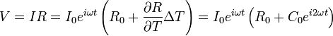
One popular technique for thermoelectric materials is a 3ω-method, in which a thin metal strip evaporated on the sample acts as heat source and a thermometer. The heater is driven with AC current at frequency ω, which causes heat source to oscillate at frequency 2ω. By monitoring AC voltage as a function of the frequency of the applied AC current thermal conductivity can be determined. The measured voltage will contain both ω and 3ω components, because the Joule heating of the film causes small perturbation to its resistance with frequency 2ω as stated in the following equation
 ,
,
where C0 is constant. Thermal conductivity is determined by the linear slope of ΔT vs. log(ω) curve. The main advantages of the 3ω-method are minimization of radiation effects and easier acquisition of the temperature dependence of the thermal conductivity than in the steady-state techniques. Although some expertise in thin film patterning and microlithography is required, this technique is considered as the best pseudo-contact method available.[4] (ch23)
Time-domain thermoreflectance method
Time-domain thermoreflectance is a method by which the thermal properties of a material can be measured, most importantly thermal conductivity. This method can be applied most notably to thin film materials, which have properties that vary greatly when compared to the same materials in bulk. The idea behind this technique is that once a material is heated up, the change in the reflectance of the surface can be utilized to derive the thermal properties. The change in reflectivity is measured with respect to time, and the data received can be matched to a model which contain coefficients that correspond to thermal properties.
Measuring devices
A thermal conductance tester, one of the instruments of gemology, determines if gems are genuine diamonds using diamond's uniquely high thermal conductivity.
For example MEASURING INSTRUMENT of HEAT CONDUCTIVITY of ITP-MG4 "Zond" (Russia)
Standards
- EN 12667, "Thermal performance of building materials and products. Determination of thermal resistance by means of guarded hot plate and heat flow meter methods. Products of high and medium thermal resistance", ISBN 0-580-36512-3.
- ISO 8301, "Thermal insulation – Determination of steady-state thermal resistance and related properties – Heat flow meter apparatus"
- ISO 8497, "Thermal insulation – Determination of steady-state thermal transmission properties of thermal insulation for circular pipes", ISBN 0-580-26907-8
- ISO 22007-2:2008 "Plastics – Determination of thermal conductivity and thermal diffusivity – Part 2: Transient plane heat source (hot disc) method"
- ISO 22007-4:2008 "Plastics – Determination of thermal conductivity and thermal diffusivity – Part 4: Laser flash method" [3]
- IEEE Standard 442–1981, "IEEE guide for soil thermal resistivity measurements", ISBN 0-7381-0794-8. See also soil thermal properties. [6]
- IEEE Standard 98-2002, "Standard for the Preparation of Test Procedures for the Thermal Evaluation of Solid Electrical Insulating Materials", ISBN 0-7381-3277-2 [7]
- ASTM Standard C518 – 10, "Standard Test Method for Steady-State Thermal Transmission Properties by Means of the Heat Flow Meter Apparatus"
- ASTM Standard D5334-08, "Standard Test Method for Determination of Thermal Conductivity of Soil and Soft Rock by Thermal Needle Probe Procedure" [8]
- ASTM Standard D5470-06, "Standard Test Method for Thermal Transmission Properties of Thermally Conductive Electrical Insulation Materials"
- ASTM Standard E1225-04, "Standard Test Method for Thermal Conductivity of Solids by Means of the Guarded-Comparative-Longitudinal Heat Flow Technique"
- ASTM Standard D5930-01, "Standard Test Method for Thermal Conductivity of Plastics by Means of a Transient Line-Source Technique"
References
- ↑ Searle's Bar for a good heat conductor. Media.paisley.ac.uk. Retrieved on 2013-12-12.
- ↑ Ian Hickson's Lees' Disc Experiment. Academia.hixie.ch. Retrieved on 2013-12-12.
- ↑ 3.0 3.1 ISO22007-4:2008 Plastics – Determination of thermal conductivity and thermal diffusivity – Part 4: Laser flash method
- ↑ Rowe, David Michael. Thermoelectrics handbook : macro to nano / edited by D.M. Rowe. Boca Raton: CRC/Taylor & Francis, 2006. ISBN 0-8493-2264-2
- ↑ http://www.stroypribor.ru/produkt/catalog/izmeriteli-teploprovodnosti/izmeritel-teploprovodnosti-itp-mg4-zond.html
- ↑ IEEE Standard 442-1981- IEEE guide for soil thermal resistivity measurements, doi:10.1109/IEEESTD.1981.81018
- ↑ IEEE Standard 98-2002 – Standard for the Preparation of Test Procedures for the Thermal Evaluation of Solid Electrical Insulating Materials, doi:10.1109/IEEESTD.2002.93617
- ↑ ASTM Standard D5334-08 – Standard Test Method for Determination of Thermal Conductivity of Soil and Soft Rock by Thermal Needle Probe Procedure, doi:10.1520/D5334-08
External links
- An alternative traditional method using real thermometers is described at .
- A brief review of new methods measuring thermal conductivity, thermal diffusivity and specific heat within a single measurement is available at .
- A brief description of Modified Transient Plance Source (MTPS) at http://patents.ic.gc.ca/opic-cipo/cpd/eng/patent/2397102/page/2397102_20120528_description.pdf