Thermal bridge


.
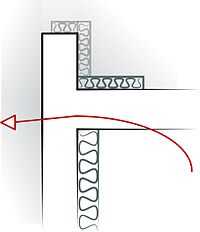
A thermal bridge, also called a cold bridge or heat bridge, is an area of an object (frequently a building) which has a significantly higher heat transfer than the surrounding materials resulting in an overall reduction in thermal insulation of the object or building.[1] Thermal bridges occur in three ways, through: materials with higher thermal conductivity than the surrounding materials,[2] penetrations of the thermal envelope, and discontinuities or gaps in the insulation material.[1]
Thermal bridging in buildings reduces energy efficiency and can allow condensation (moisture) and thermal comfort problems. Condensation can result in indoor air quality problems and building deterioration.
Thermal bridging is prevented by careful design applying materials to achieve a uniform thermal resistance such as thermal breaks and continuous insulation.
Concept

Low-energy buildings use a thermal insulation layer that carefully enclosures the whole building without any missed area, which means no "holes" in the insulation. If there are, heat transfers significantly through any "hole", greatly reducing the whole system of insulation. Thermal bridges are characterized by multi-dimensional heat transfer, and therefore they cannot be adequately approximated by the one-dimensional models of calculation typically used in norms and standards for the thermal performance of buildings (U-values). Surface moisture due to condensation, typically occurring in such regions as floor-wall connections and window installations, as well as mold growth in humid environments can also be effectively prevented by means of multi-dimensional evaluation during planning and detail design.
Examples

- Concrete balconies that extend the floor slab through the building envelope are common examples of thermal bridging.
- In commercial construction, steel or concrete members incorporated in exterior wall or roof construction often form thermal bridges.[3]
- Metal ties in cavity walls are another type of thermal bridge commonly found in masonry construction.[3]
- Partially insulated, because thermal bridges are not considered by the calculation procedure, have been shown with actual thermal losses up to 35% higher than initially estimated.[4]
Thermal Bridges and Building Enclosure Types
Thermal bridges take places commonly in reinforced concrete exterior walls surrounding seismic columns, ring beams, lintels doors, reinforced concrete or steel frame beams, columns, reinforced concrete or metal roof in a small side ribs, and metal curtain wall glazing where the metal frame and window extrude to outside.
While thermal bridges exist in various types of building enclosures, two types show significant reduced R-value caused by thermal bridges, masonry and curtain wall.


Masonry buildings
Concrete floors and edge beams, especially at the corners, are common thermal bridges. Physical heat conductivity for concrete material are 2~4 times higher than ordinary brick materials, which are usually used for facade enclosures. Meanwhile, if the indoor environment is not vented enough, the brick material will slowly absorb rainwater and also humidity into the wall. When the temperature difference between indoor and outdoor space is large, the indoor warm and humid air could condense in this area. Insulation layer’s R-value will be reduced significantly by humidity, thus the thermal performance for insulation wall is not evenly distributed.[5] The more humidity, the worse thermal performance. This uneven distribution finally cause thermal bridge for large area, sometimes the whole enclosure system.Because of multiple factors such as orientation, daylight, ventilation, temperature and human factors, the distribution of thermal bridge could also be uneven for a single building, which accounts for the phenomena that sometimes while some units are severely affected by thermal distribution together with mildew, some units are slightly affected.
Curtain wall
Because curtain wall frames are made of highly conductive aluminum, which is about four times more conductive than steel, and typically go from the exterior of the building through to the interior, they are thermal bridges.[6]
Thermal Bridging in Construction
Thermal bridge classification


The building enclosure system provides a separation of interior physical environment from the exterior physical environment. While HVAC system are based on air tightness, control of diffusive vapor transfer, and thermal efficiency, there are three major systems that require careful-designed continuity: the air barrier system, the water barrier system and the thermal barrier system. In architectural detailed design and construction, scenarios providing chances penetrating this continuous layer are listed as below:
- Repeating thermal bridges - where bridges occur following a regular pattern, such that made by wall ties penetrating a cavity wall
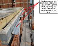
- Non-repeating thermal bridges - such as the bridging of a cavity wall by a single lintel
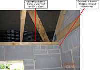
- Geometrical thermal bridges - placed at the junction of two planes, such as at the corner of a wall
Insulation requirements relating to thermal bridging
There are many different materials that are used for insulation, and new ones are often being created as the need for energy efficiency, sustainable design, and cheaper costs are currently what are driving new innovation. Currently, the types of insulation that are being used are:
- Fiberglass or rock wool insulation
- Insulating glass or polystyrene rigid board insulation, formed-in-place polyurethane insulation
- Cellulose/perlite/vermiculite loose fill, and insulated pre-cast concrete insulation.
Strategies and methods to reduce thermal bridges in practical construction

Multiple situations and interfaces could provide thermal bridges, these are classified as: roof-to-wall; steel stud construction, window-to-wall, wall-to-balcony slab; wall-to-wall; and sunshade-to-wall.[6]
While various methods are applied to each of these situations, several principles are followed methodologically:
- A continuous thermal barrier is needed in the building enclosure; the location of this barrier for most buildings should be outboard of highly conductive materials.
- Reduction and elimination of potential and actual thermal bridges are needed.
- Lapping of insulation where direct continuity is not possible can mitigate thermal bridges.
- Window-to-wall interfaces create additional challenges that need to be carefully reviewed for energy considerations and condensation risk due to positioning of the fenestration within the rest of the assembly.
- Reducing and limiting thermal bridging in buildings will typically reduce energy needs for the building.
Current one-dimensional analysis and challenge
One-dimensional analysis is based on simple, steady state, flow of heat, which means that heat is driven by a temperature differences that does not fluctuate so that heat flow is always in one direction. The product (kA) of thermal conductivity (k) and cross sectional area (A) of the heat flow path can be used in evaluating heat flow. .
While most energy calculating software could only supply 1D heat flow analysis,[7] actually it is a 3D problem to understand thermal bridges, where there's the challenge for technical modeling software. Currently better methods and modeling software are still under research.
See also
References
- ↑ 1.0 1.1 Gorse, Christopher A., and David Johnston. "thermal bridge" 'Oxford Dictionary of Construction, Surveying, and Civil Engineering. 3rd ed. Oxford: Oxford UP, 2012. 440-441. Print.
- ↑ Binggeli, C. (2010). Building Systems for Interior Designers. Hoboken, NJ: John Wiley & Sons.
- ↑ 3.0 3.1 Allen, E. and J. Lano, Fundamentals of Building Construction: materials and methods. Hoboken, NJ: John Wiley & Sons. 2009.
- ↑ Theodosiou, T. G.; Papadopoulos, A. M. (2008). "The impact of thermal bridges on the energy demand of buildings with double brick wall constructions". Energy and Buildings 40 (11): 2083–2089. doi:10.1016/j.enbuild.2008.06.006.
- ↑ Matilainen, Miimu; Jarek, Kurnitski (2002). "Moisture conditions in highly insulated outdoor ventilated crawl spaces in cold climates". Energy and buildings 35 (2): 175–187. doi:10.1016/S0378-7788(02)00029-4.
- ↑ 6.0 6.1 Totten, Paul E.; O’Brien, Sean M. (2008). "The Effects of Thermal Bridging at Interface Conditions". Building Enclosure Science & Technology.
- ↑ Chu, R.C. (1982). "Conduction Cooling for an LSI Package: A One-Dimensional Approach". IBM Journal of Research and Development 26 (1): 45–54. doi:10.1147/rd.261.0045.
External links
| Wikimedia Commons has media related to Thermal bridges. |
- Design Guide: Solutions to Prevent Thermal Bridging.
- Manufactured Structural Thermal Breaks.
- EU IEE SAVE Project ASIEPI: topic 'Thermal bridges' - An effective handling of thermal bridges in the EPBD context
- Passivhaus Institute: Thermal Bridges in construction - how to avoid them
- A bridge too far - ASHRAE Journal article on thermal bridging
- International Building Code, 2009: Interior Environment
- Online Energy2D simulation of thermal bridge (Java required)
- What Defines Thermal Bridge Free Design