Switched reluctance motor
The switched reluctance motor (SRM) is a type of a stepper motor, an electric motor that runs by reluctance torque. Unlike common DC motor types, power is delivered to windings in the stator (case) rather than the rotor. This greatly simplifies mechanical design as power does not have to be delivered to a moving part, but it complicates the electrical design as some sort of switching system needs to be used to deliver power to the different windings. With modern electronic devices, precisely timed switching is not a problem, and the SRM (Switched Reluctance Motor) is a popular design for modern stepper motors. Its main drawback is torque ripple. An alternate use of the same mechanical design is as a generator when driven mechanically, and the load is switched to the coils in sequence to synchronize the current flow with the rotation. Such generators can be run at much higher speeds than conventional types as the armature can be made as one piece of magnetisable material, a simple slotted cylinder . [1] In this case use of the abbreviation SRM is extended to mean Switched Reluctance Machine, although SRG, Switched Reluctance Generator is also used. A topology that is both motor and generator is useful for starting the prime mover, as it saves a dedicated starter motor.
Operating principle
The SRM has wound field coils as in a DC motor for the stator windings. The rotor however has no magnets or coils attached. It is a solid salient-pole rotor (having projecting magnetic poles) made of soft magnetic material (often laminated-steel). When power is applied to the stator windings, the rotor's magnetic reluctance creates a force that attempts to align the rotor pole with the nearest stator pole. In order to maintain rotation, an electronic control system switches on the windings of successive stator poles in sequence so that the magnetic field of the stator "leads" the rotor pole, pulling it forward. Rather than using a troublesome high-maintenance mechanical commutator to switch the winding current as in traditional motors, the switched-reluctance motor uses an electronic position sensor to determine the angle of the rotor shaft and solid state electronics to switch the stator windings, which also offers the opportunity for dynamic control of pulse timing and shaping. This differs from the apparently similar induction motor which also has windings that are energised in a rotating phased sequence, in that the magentization of the rotor is static (a salient pole that is made 'North' remains so as the motor rotates) while an induction motor has slip, and rotates at slightly less than synchronous speed. This absence of slip makes it possible to know the rotor position exactly, and the motor can be stepped arbitrarily slowly.
Simple switching
If the poles A0 and A1 are energised then the rotor will align itself with these poles. Once this has occurred it is possible for the stator poles to be de-energised before the stator poles of B0 and B1 are energized. The rotor is now positioned at the stator poles b. This sequence continues through c before arriving back at the start. This sequence can also be reversed to achieve motion in the opposite direction. This sequence can be found to be unstable while in operation, under high load, or high acceleration or deceleration, a step can be missed, and the rotor jumps to wrong angle, perhaps going back one instead of forward three.

Improved sequence
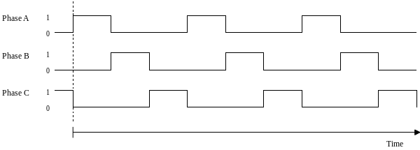
A much more stable system can be found by using the following "quadrature" sequence. First, stator poles A0 and A1 are energized. Then stator poles of B0 and B1 are energized which pulls the rotor so that it is aligned in between the stator poles of A and B. Following this the stator poles of A are de-energized and the rotor continues on to be aligned with the stator poles of B, this sequence continues through BC, C and CA before a full rotation has occurred. This sequence can also be reversed to achieve motion in the opposite direction. As at any time two coils are energised, and there are more steps between positions with identical magnetisation, so the onset of missed steps occurs at higher speeds or loads.

In addition to more stable operation, this approach provides a well-timed sequence as the timings of the phase being both on and off are equal, rather than being at a 1:2 ratio as in the simpler sequence.
Control
The control system is responsible for giving the required sequential pulses to the power circuitry in order to activate the phases as required. While it is possible to do this using electro-mechanical means such as commutators or simple analog or digital timing circuits, more control is possible with more advanced methods.
Many controllers in use incorporate programmable logic controllers (PLCs) rather than electromechanical components in their implementation. A microcontroller is also ideal for this kind of application since it enables a very precise control of the phase activation timings. It also gives the possibility of implementing a soft start function in software form, in order to reduce the amount of hardware required.
Power circuitry

The most common approach to the powering of a switched reluctance motor is to use an asymmetric bridge converter.
There are 3 phases in an asymmetric bridge converter corresponding to the phases of the switched reluctance motor. If both of the power switches on either side of the phase are turned on, then that corresponding phase shall be actuated. Once the current has risen above the set value, the switch shall turn off. The energy now stored within the motor winding shall now maintain the current in the same direction until that energy is depleted.

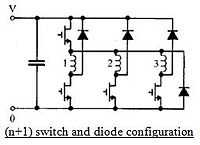
This basic circuitry may be altered so that fewer components are required although the circuit shall perform the same action. This efficient circuit is known as the (n+1) switch and diode configuration.
A capacitor, in either configuration, is used to suppress electrical and acoustic noise by limiting fluctuations in the supply voltage.
References
External links
| Wikimedia Commons has media related to Switched reluctance machines. |
- Switched Reluctance Motor Drives
- Real-Time Simulation and Control of Reluctance Motor Drives for High Speed Operation with Reduced Torque Ripple
| ||||||||||||||||||||||||||||||||||||||||||||||||||||||||||||||||||||||||||