Stokes parameters
The Stokes parameters are a set of values that describe the polarization state of electromagnetic radiation. They were defined by George Gabriel Stokes in 1852,[1] as a mathematically convenient alternative to the more common description of incoherent or partially polarized radiation in terms of its total intensity (I), (fractional) degree of polarization (p), and the shape parameters of the polarization ellipse. The effect of an optical system on the polarization of light can be determined by constructing the Stokes vector for the input light and applying Mueller calculus, to obtain the Stokes vector of the light leaving the system.
Definitions
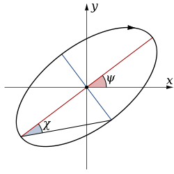

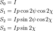
The relationship of the Stokes parameters to intensity and polarization ellipse parameters is shown in the equations below and the figure at right.
Here 
 ,
,  and
and  are the spherical coordinates of the three-dimensional vector of cartesian coordinates
  .
.  is the total intensity of the beam, and
  is the degree of polarization. The factor of two before
  represents the fact that any polarization ellipse is indistinguishable from one rotated by 180°, while the factor of two before
  indicates that an ellipse is indistinguishable from one with the semi-axis lengths swapped accompanied by a 90° rotation. The four Stokes parameters are sometimes denoted I, Q, U and V, respectively.
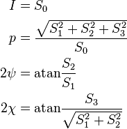
If given the Stokes parameters one can solve for the spherical coordinates with the following equations:
Stokes vectors
The Stokes parameters are often combined into a vector, known as the Stokes vector:
The Stokes vector spans the space of unpolarized, partially polarized, and fully polarized light. For comparison, the Jones vector only spans the space of fully polarized light, but is more useful for problems involving coherent light. The four Stokes parameters do not form a preferred basis of the space, but rather were chosen because they can be easily measured or calculated.
Examples
Below are shown some Stokes vectors for common states of polarization of light.

Linearly polarized (horizontal) 
Linearly polarized (vertical) 
Linearly polarized (+45°) 
Linearly polarized (−45°) 
Right-hand circularly polarized 
Left-hand circularly polarized 
Unpolarized
Alternate explanation
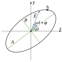
A monochromatic plane wave is specified by its propagation vector,  , and the complex amplitudes of the electric field,
  and
and  , in a basis
  . Alternatively, one may specify the propagation vector, the phase,
  , and the polarization state,
  , where
  is the curve traced out by the electric field in a fixed plane. The most familiar polarization states are linear and circular, which are degenerate cases of the most general state, an ellipse.
One way to describe polarization is by giving the semi-major and semi-minor axes of the polarization ellipse, its orientation, and the sense of rotation (See the above figure). The Stokes parameters  ,
,  ,
,  , and
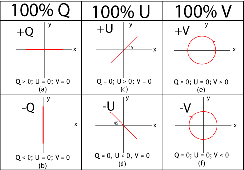
, and  , provide an alternative description of the polarization state which is experimentally convenient because each parameter corresponds to a sum or difference of measurable intensities. The next figure shows examples of the Stokes parameters in degenerate states.
Definitions
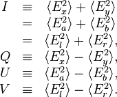
The Stokes parameters are defined by
where the subscripts refer to three bases: the standard Cartesian basis ( ), a Cartesian basis rotated by 45° (
 ), and a circular basis (
 ). The circular basis is defined so that
  . The next figure shows how the signs of the Stokes parameters are determined by the helicity and the orientation of the semi-major axis of the polarization ellipse.

Representations in fixed bases
In a fixed ( ) basis, the Stokes parameters when using an increasing phase convention are
while for  , they are
and for  , they are
Properties
For purely monochromatic coherent radiation, one can show that
whereas for the whole (non-coherent) beam radiation, the Stokes parameters are defined as averaged quantities, and the previous equation becomes an inequality:[2]
However, we can define a total polarization intensity  , so that
where  is the total polarization fraction.
Let us define the complex intensity of linear polarization to be
Under a rotation  of the polarization ellipse, it can be shown that
  and
and  are invariant, but
With these properties, the Stokes parameters may be thought of as constituting three generalized intensities:
where  is the total intensity,
  is the intensity of circular polarization, and
  is the intensity of linear polarization. The total intensity of polarization is
  , and the orientation and sense of rotation are given by
Since  and
and  , we have
Relation to the polarization ellipse
In terms of the parameters of the polarization ellipse, the Stokes parameters are
Inverting the previous equation gives
See also
- Mueller calculus
- Jones calculus
- Polarization (waves)
- Rayleigh Sky Model
- Stokes operators
- Polarization mixing
Notes
References
- E. Collett, Field Guide to Polarization, SPIE Field Guides vol. FG05, SPIE (2005). ISBN 0-8194-5868-6.
- E. Hecht, Optics, 2nd ed., Addison-Wesley (1987). ISBN 0-201-11609-X.
- William H. McMaster (1954). "Polarization and the Stokes Parameters". Am. J. Phys. 22: 351. Bibcode:1954AmJPh..22..351M. doi:10.1119/1.1933744.
- William H. McMaster (1961). "Matrix representation of polarization". Rev. Mod. Phys. 8: 33. Bibcode:1961RvMP...33....8M. doi:10.1103/RevModPhys.33.8.
