South African Class 6E1, Series 3
| South African Class 6E1, Series 3 | |
|---|---|
|
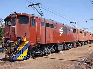
No. E1306 at Beaconsfield Depot, Kimberley, 25 August 2007 | |
| Type and origin | |
| Power type | Electric |
| Designer | Union Carriage and Wagon |
| Builder | Union Carriage and Wagon |
| Model | UCW 6E1 |
| Build date | 1971-1973 |
| Total produced | 150 |
| Specifications | |
| UIC classification | Bo-Bo |
| Gauge | 3 ft 6 in (1,067 mm) Cape gauge |
| Bogies | 3.430 m (11 ft 3 in) wheelbase |
| Wheel diameter | 1,220 mm (48 in) |
| Wheelbase | 11.279 m (37 ft 0.1 in) |
| Length | 15.494 m (50 ft 10 in) |
| Width | 2.896 m (9 ft 6 in) |
| Height | 4.089 m (13 ft 5 in) pantographs down |
| Axle load | 22,226 kg (21.9 long tons) |
| Locomotive weight | 88,904 kg (87.5 long tons) |
| Current collection method | Pantographs |
| Traction motors | Four AEI 283 AZ |
| Transmission | 18/67 gear ratio |
| Performance figures | |
| Maximum speed | 113 km/h (70 mph) |
| Power output |
Per motor: 623 kW (835 hp) 1 hour 563 kW (755 hp) continuous Total: 2,492 kW (3,342 hp) 1 hour 2,252 kW (3,020 hp) continuous |
| Tractive effort |
311 kN (70,000 lbf) starting 221 kN (50,000 lbf) 1 hour 193 kN (43,000 lbf) continuous at 40 km/h (25 mph) |
| Locomotive brake | Air & Regenerative |
| Train brakes | Air & Vacuum |
| Career | |
| Operator(s) |
South African Railways Spoornet Transnet Freight Rail |
| Class | Class 6E1 |
| Power class | 3 kV DC |
| Number in class | 150 |
| Number(s) | E1296-E1445 [1] |
| Delivered | 1971-1973 |
| First run | 1971 |
The South African Class 6E1, Series 3 of 1971 is a South African electric locomotive from the South African Railways era.
Between 1971 and 1973 the South African Railways placed one hundred and fifty Class 6E1, Series 3 electric locomotives with a Bo-Bo wheel arrangement in mainline service.[1]
Manufacturer
The 3 kV DC Class 6E1, Series 3 electric locomotive was designed and built for the South African Railways (SAR) by Union Carriage and Wagon (UCW) in Nigel, Transvaal, with the electrical equipment supplied by the General Electric Company (GEC).[2]
One hundred and fifty locomotives were delivered between 1971 and 1973, numbered in the range from E1296 to E1445. UCW did not allocate builder’s numbers to the locomotives it built for the SAR and used the SAR unit numbers for their record keeping.[1]
Characteristics
Bogies
The Class 6E1 was built with sophisticated traction linkages on their bogies and with stabilisers mounted between the linkages on the bogies and the locomotive body. Together with its electronic wheelslip detection system, these traction linkages and stabilisers ensure the maximum transfer of power to the rails without causing wheelslip.[3]
Orientation
These dual cab locomotives have a roof access ladder on one side only, just to the right of the cab access door. The roof access ladder end is marked as the number 2 end. A passage along the centre of the locomotive connects the cabs, which are identical apart from the fact that the handbrake is located in cab 2. A pantograph hook stick is stowed in a tube mounted below the lower edge of the locomotive body on the roof access ladder side. The locomotive has three small panels along the lower half of the body on the roof access ladder side, and only one panel on the opposite side.[1]
Series identifying features
The Class 6E1 was produced in eleven series over a period of nearly sixteen years, with altogether nine hundred and sixty units placed in service, all built by UCW. This makes the Class 6E1 the most numerous single locomotive class ever to have seen service in South Africa and serves as ample proof of a highly successful design.[1][3]
While some Class 6E1 series are visually indistinguishable from their predecessors or successors, some externally visible changes did occur over the years. Series 1 locomotives had their sandboxes mounted on the bogies, while Series 2 to 11 had their sandboxes mounted along the bottom edge of the locomotive body, with the sandbox lids fitting into recesses in the body.[1]
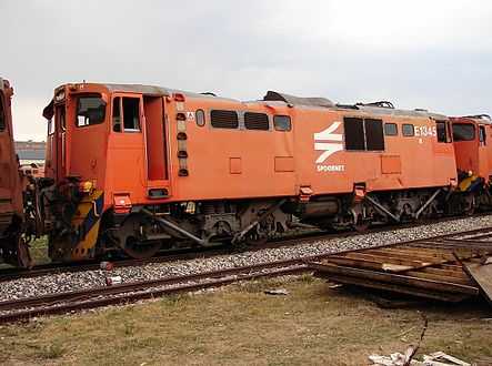
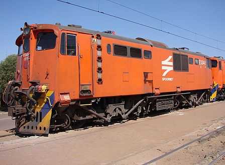
The fifty Series 2 and the first fifty Series 3 locomotives are visually indistinguishable from each other. On Series 3 locomotives in the number range from E1346 to E1445 an externally visible difference is a wider stirrup middle step below their side doors. The two different stirrups are illustrated in the pictures of numbers E1345 and E1346 below.[1][4][5]
This appears to indicate that Series 2 should actually have consisted of one hundred locomotives and not fifty, firstly since these locomotives, numbers E1246 to E1345, are identical in exterior appearance, and secondly since Series 4, 5 and 6 were all delivered in batches of one hundred.[1][4][5]
If that had been the case, Series 2 and 3 would also have consisted of one hundred locomotives each, numbered in the ranges from E1246 to E1345 and E1346 to E1445 respectively, instead of fifty and one hundred and fifty as they were officially designated, numbered in the ranges from E1246 to E1295 and E1296 to E1445 respectively.[4][5]
-
No. E1345 with its narrow stirrup at Koedoespoort, Pretoria on 9 October 2009
-
No. E1346 with its wide stirrup at Beaconsfield Depot on 25 August 2007
Operation
Startup
When there is no compressed air in the locomotive's system to raise a pantograph to start up, a pantograph hook stick is used to manually raise the pantograph. This starts the high voltage motor that drives the auxiliary alternator to supply 110V power to start the compressor and power other control circuits. Once there is enough main air pressure to keep the pantograph in the raised position, the pantograph hook stick can be dropped.[6]
The locomotive is controlled via resistors over which the voltage is dropped in a configuration of series and parallel electrical circuits. The circuit breakers that switch these circuits work under very high power and voltage and are therefore all pneumatically operated for insulation purposes. Compressed air is required to open or close the switch actions and air is also used for the weakfield cam switch, which also switches under very high currents.[6]
Running
Upon starting off and in the low notches the major part of the voltage is dropped over the banks of resistors and all four traction motors are in series.[6] The blowers that accelerate the dissipation of heat in the resistor banks give the Class 6E its very distinctive sound, a deep and loud whine when power is applied.[7]
As the driver notches up, some of the resistor banks are cut out via the pneumatically operated switches and the voltage increases across the traction motors. The more resistors that are cut out as the driver notches higher, the more power is developed by the traction motors. At around 22 to 28 kilometres per hour (14 to 17 miles per hour) the locomotive switches to a parallel combination, where the two traction motors per bogie are in a series electrical circuit while the two bogies are in parallel electrical circuit. Eventually, when all resistors are cut out, the locomotive is operating in full-field.[6]
When the traction motors are operated in full-field, be it in series or parallel mode, they are performing at maximum power for normal operation. To increase the speed at this point, if necessary, higher power output is required from the traction motors. The only way to increase power is to force a higher current flow. To accomplish this, the weakfield cam switch switches resistance in parallel with the field coils, which reduces the overall resistance of the field coils. This increases the magnetic flux and more power is generated by the traction motors over short periods.[6]
Brakes
The locomotive itself used air brakes, but it was equipped to operate trains with air or vacuum brakes. The brake system would be set up for either air or vacuum train working by means of a turning switch on the driver's brake valve and by pre-setting the appropriate brake valves in the passage.
The Class 6E1 locomotives were built with an air brake system consisting of various valves connected to each other with pipes, commonly referred to as a “bicycle frame” brake system. The compressed air pipes run under the locomotive's belly in a zig-zag pattern, going through bolster and other members to extend its length to allow the maximum amount of moisture to condense on the way to the reservoirs. As a result it has multiple pipe connections. A weakness of the system was that, after an accident or even a hard coupling, these pipes tended to develop leaks at the joints that were extremely difficult to repair.[8]
While hauling a vacuum braked train, the locomotive's air brake system would be disabled and the train would be controlled using the train brakes alone to slow down and stop. While hauling an air braked train, on the other hand, the locomotive brakes would engage along with the train brakes. While working either type of train downgrade, the locomotive's regenerative braking system would also work in conjunction with the train brakes.
When the locomotive was stopped, the air brakes on both bogies were applied together. The handbrake or parking brake, located in Cab no. 2, only operated on the unit's last axle, or no. 7 and 8 wheels.
Service
The Class 6E1 family saw service all over both of the 3 kV DC mainline and branchline networks, the smaller Cape Western network between Cape Town and Beaufort West and the larger network that covers portions of the Northern Cape, the Free State, Natal, Gauteng, North West Province and Mpumalanga.[9]
Reclassification and rebuilding
Reclassification to Class 16E
During 1990 and 1991 Spoornet semi-permanently coupled several pairs of otherwise largely unmodified Class 6E1 locomotives, reclassified them to Class 16E and allocated a single locomotive number to each pair, with the individual locomotives in the pairs inscribed "A" or "B". The aim was to accomplish savings on cab maintenance by coupling the locomotives at their number 1 ends, abandoning the number one end cabs in terms of maintenance and using only the number two end cabs.[9]
One such pair was made up of two Series 3 locomotives, numbers E1418 and E1419, which became Class 16E number 16-227A and B respectively.[9]
Rebuilding to Class 18E
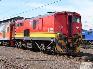
Beginning in 2000, Spoornet began a project to rebuild Series 2 to 11 Class 6E1 locomotives to Class 18E, Series 1 and Series 2 at the Transnet Rail Engineering (TRE) workshops at Koedoespoort. In the process the cab at the number 1 end was stripped of all controls and the driver's front and side windows were blanked off in order to have a toilet installed, thereby forfeiting the loco's bi-directional ability.[9][10]
Since the driving cab's noise level had to be below 85 decibels, cab 2 was selected as the Class 18E driving cab primarily based on its lower noise level compared to cab 1, which is closer and more exposed to the compressor's noise and vibration. Another factor was the closer proximity of cab 2 to the low voltage switch panel. The fact that the handbrake was located in cab 2 was not a deciding factor, but was considered an additional benefit.[10]
The known Class 6E1, Series 3 locomotives that were used in this project were all rebuilt to Class 18E, Series 2 locomotives. Their numbers and renumbering details are shown in the table.[10]
Count |
6E1 no. |
Year built |
18E no. |
18E series |
Year rebuilt |
Notes |
|---|---|---|---|---|---|---|
| 1 | E1297 | 1971-72 | 18-761 | 2 | 2013 | |
| 2 | E1298 | 1971-72 | 18-776 | 2 | 2013 | c. 2013 |
| 3 | E1300 | 1971-72 | 18-435 | 2 | 2013 | PRASA |
| 4 | E1303 | 1971-72 | 18-651 | 2 | 2011 | |
| 5 | E1310 | 1971-72 | 18-764 | 2 | 2013 | |
| 6 | E1311 | 1971-72 | 18-695 | 2 | 2012 | |
| 7 | E1313 | 1971-72 | 18-672 | 2 | 2011 | |
| 8 | E1315 | 1971-72 | 18-681 | 2 | 2011 | |
| 9 | E1316 | 1971-72 | 18-704 | 2 | 2012 | |
| 10 | E1319 | 1971-72 | 18-707 | 2 | 2012 | |
| 11 | E1320 | 1971-72 | 18-788 | 2 | 2014 | c. 2014 |
| 12 | E1322 | 1971-72 | 18-677 | 2 | 2012 | |
| 13 | E1323 | 1971-72 | 18-682 | 2 | 2012 | |
| 14 | E1325 | 1971-72 | 18-679 | 2 | 2012 | |
| 15 | E1326 | 1971-72 | 18-743 | 2 | 2013 | |
| 16 | E1327 | 1971-72 | 18-791 | 2 | 2014 | c. 2014 |
| 17 | E1329 | 1972 | 18-807 | 2 | 2014 | |
| 18 | E1330 | 1972 | 18-806 | 2 | 2014 | |
| 19 | E1331 | 1972 | 18-706 | 2 | 2012 | |
| 20 | E1336 | 1972 | 18-678 | 2 | 2011 | |
| 21 | E1337 | 1972 | 18-676 | 2 | 2011 | |
| 22 | E1343 | 1972 | 18-759 | 2 | 2013 | |
| 23 | E1346 | 1972 | 18-748 | 2 | 2013 | |
| 24 | E1353 | 1972 | 18-771 | 2 | 2013 | |
| 25 | E1358 | 1972 | 18-721 | 2 | 2012 | |
| 26 | E1361 | 1972 | 18-766 | 2 | 2013 | |
| 27 | E1363 | 1972 | 18-684 | 2 | 2012 | |
| 28 | E1367 | 1972 | 18-732 | 2 | 2013 | |
| 29 | E1369 | 1972 | 18-724 | 2 | 2013 | |
| 30 | E1370 | 1972 | 18-793 | 2 | 2014 | c. 2014 |
| 31 | E1371 | 1972 | 18-680 | 2 | 2011 | |
| 32 | E1372 | 1972 | 18-745 | 2 | 2013 | |
| 33 | E1375 | 1972 | 18-683 | 2 | 2011 | |
| 34 | E1379 | 1972 | 18-434 | 2 | 2013 | PRASA |
| 35 | E1380 | 1972 | 18-812 | 2 | 2014 | |
| 36 | E1385 | 1972 | 18-427 | 2 | 2013 | PRASA |
| 37 | E1386 | 1972 | 18-685 | 2 | 2011 | |
| 38 | E1390 | 1972-73 | 18-689 | 2 | 2011 | |
| 39 | E1397 | 1972-73 | 18-430 | 2 | 2013 | PRASA |
| 40 | E1399 | 1973 | 18-646 | 2 | 2010 | |
| 41 | E1400 | 1973 | 18-653 | 2 | 2011 | |
| 42 | E1402 | 1973 | 18-775 | 2 | 2013 | c. 2013 |
| 43 | E1406 | 1973 | 18-747 | 2 | 2013 | |
| 44 | E1407 | 1973 | 18-773 | 2 | 2013 | |
| 45 | E1408 | 1973 | 18-735 | 2 | 2013 | |
| 46 | E1410 | 1973 | 18-796 | 2 | 2014 | c. 2014 |
| 47 | E1413 | 1973 | 18-783 | 2 | 2014 | c. 2014 |
| 48 | E1414 | 1973 | 18-423 | 2 | 2012 | PRASA |
| 49 | E1415 | 1973 | 18-760 | 2 | 2013 | |
| 50 | E1416 | 1973 | 18-744 | 2 | 2013 | |
| 51 | E1419 | 1973 | 18-790 | 2 | 2014 | c. 2014 |
| 52 | E1421 | 1973 | 18-702 | 2 | 2012 | |
| 53 | E1422 | 1973 | 18-655 | 2 | 2011 | |
| 54 | E1428 | 1973 | 18-652 | 2 | 2011 | |
| 55 | E1429 | 1973 | 18-850 | 2 | Uncompleted | |
| 56 | E1430 | 1973 | 18-762 | 2 | 2013 | |
| 57 | E1433 | 1973 | 18-782 | 2 | 2014 | c. 2014 |
| 58 | E1434 | 1973 | 18-432 | 2 | 2013 | PRASA |
| 59 | E1437 | 1973 | 18-422 | 2 | 2012 | PRASA |
| 60 | E1441 | 1973 | 18-808 | 2 | 2014 | |
| 61 | E1442 | 1973 | 18-673 | 2 | 2011 | |
The Blue Train
In the SAR and Spoornet eras, when the official liveries were Gulf Red and yellow whiskers for the SAR, and initially orange and later maroon for Spoornet, many selected electric locomotives and some diesel-electrics were painted blue for use with the Blue Train, but without altering the layout of the various paint schemes. Blue Train locomotives were therefore blue with yellow whiskers in the SAR era, blue with the Spoornet logo and "SPOORNET" in Spoornet’s orange era, and blue with the Spoornet logo but without "SPOORNET" in Spoornet’s maroon era. Later, in Spoornet’s blue era, there was no need for a separate Blue Train livery, while in the Transnet Freight Rail (TFR) era one Class 14E and the surviving Class 14E1 electric locomotives were eventually repainted in blue during 2012 for use with the Blue Train.[9][11][12]
All but five of the Class 6E1, Series 3 locomotives were delivered in the SAR Gulf Red and yellow whiskers livery. The five exceptions, numbers E1341 to E1345, were delivered in blue with yellow whiskers for use with the Blue Train between the Rand and Kimberley. In about 1985 these five were replaced by the five ex MetroBlitz Class 12E locomotives that were then all repainted in blue and whiskers. The five Series 3 locomotives were all eventually repainted in Spoornet’s orange livery.[9]
Liveries illustrated
The main picture shows E1306 in the Spoornet maroon livery at Beaconsfield Depot in Kimberley on 25 August 2007. Illustrated below are some of the other liveries that Series 3 locomotives served in.
-
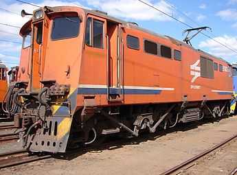
No. E1329 in Spoornet lined orange livery at Ladysmith, 5 August 2007
-
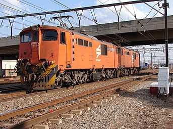
No. E1377 in Spoornet orange livery at Kaalfontein, 23 September 2009
-
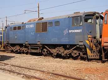
No. E1365 in Spoornet blue with solid numbers, Sentrarand, 22 September 2009
-
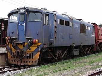
No. E1399 in Spoornet blue with outline numbers at Koedoespoort, 9 October 2009
-
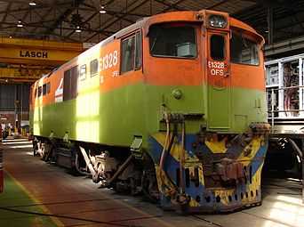
No. E1328 being repainted in a unique livery at Sentrarand, 22 September 2009
-
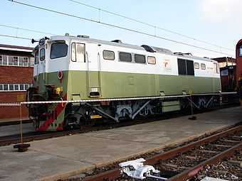
No. E1328 as trade test locomotive at Sentrarand, 18 May 2013
See also
- Electric locomotive numbering and classification
- List of South African locomotive classes
- South African Class 6E1, Series 1
- South African Class 6E1, Series 2
- South African Class 6E1, Series 4
- South African Class 6E1, Series 5
- South African Class 6E1, Series 6
- South African Class 6E1, Series 7
- South African Class 6E1, Series 8
- South African Class 6E1, Series 9
- South African Class 6E1, Series 10
- South African Class 6E1, Series 11
- South African Class 16E
- South African Class 18E, Series 2
- South African locomotive history
References
|
- ↑ 1.0 1.1 1.2 1.3 1.4 1.5 1.6 1.7 South African Railways Index and Diagrams Electric and Diesel Locomotives, 610mm and 1065mm Gauges, Ref LXD 14/1/100/20, 28 January 1975, as amended
- ↑ "UCW - Electric locomotives" (PDF). The UCW Partnership. Archived from the original (PDF) on 12 October 2007. Retrieved 30 September 2010.
- ↑ 3.0 3.1 Paxton, Leith; Bourne, David (1985). Locomotives of the South African Railways (1st ed.). Cape Town: Struik. pp. 128–129. ISBN 0869772112.
- ↑ 4.0 4.1 4.2 E1345 with narrow stirrup
- ↑ 5.0 5.1 5.2 E1346 with wide stirrup
- ↑ 6.0 6.1 6.2 6.3 6.4 Operation - South African Classes 6E, 6E1, 16E, 17E and 18E
- ↑ Dulez, Jean A. (2012). Railways of Southern Africa 150 Years (Commemorating One Hundred and Fifty Years of Railways on the Sub-Continent - Complete Motive Power Classifications and Famous Trains - 1860-2011) (1st ed.). Garden View, Johannesburg, South Africa: Vidrail Productions. p. 297. ISBN 9 780620 512282.
- ↑ Information obtained from Transnet engineers and drivers
- ↑ 9.0 9.1 9.2 9.3 9.4 9.5 Railways of Southern Africa Locomotive Guide, 2002 Edition, (Compiled by John N. Middleton), p57, as amended by Combined Amendment List 4, January 2009
- ↑ 10.0 10.1 10.2 Information gathered from the rebuild files of individual locomotives at Transnet Rail Engineering’s Koedoespoort shops, or obtained from John Middleton as well as several Transnet employees
- ↑ E1973 in blue based on orange livery
- ↑ E1951 in blue based on maroon livery