South African Class 6E1, Series 10
| South African Class 6E1, Series 10 | |
|---|---|
|
No. E2133 at Nelspruit, Eastern Transvaal, 22 October 1990 | |
| Type and origin | |
| Power type | Electric |
| Designer | Union Carriage & Wagon |
| Builder | Union Carriage & Wagon |
| Model | UCW 6E1 |
| Build date | 1982-1984 |
| Total produced | 55 |
| Specifications | |
| UIC classification | Bo-Bo |
| Gauge | 3 ft 6 in (1,067 mm) Cape gauge |
| Bogies | 3.430 m (11 ft 3 in) wheelbase |
| Wheel diameter | 1,220 mm (48 in) |
| Wheelbase | 11.279 m (37 ft 0.1 in) |
| Length | 15.494 m (50 ft 10 in) |
| Width | 2.896 m (9 ft 6 in) |
| Height | 4.089 m (13 ft 5 in) pantographs down |
| Axle load | 22,447 kg (22.1 long tons) |
| Locomotive weight | 89,788 kg (88.4 long tons) |
| Current collection method | Pantographs |
| Traction motors | Four AEI 283 AY |
| Transmission | 18/67 gear ratio |
| Performance figures | |
| Maximum speed | 113 km/h (70 mph) |
| Power output |
Per motor: 623 kW (835 hp) 1 hour 563 kW (755 hp) continuous Total: 2,492 kW (3,342 hp) 1 hour 2,252 kW (3,020 hp) continuous |
| Tractive effort |
311 kN (70,000 lbf) starting 221 kN (50,000 lbf) 1 hour 193 kN (43,000 lbf) continuous at 40 km/h (25 mph) |
| Locomotive brake | Air & Regenerative |
| Train brakes | Air & Vacuum |
| Career | |
| Operator(s) |
South African Railways Spoornet |
| Class | Class 6E1 |
| Power class | 3 kV DC |
| Number in class | 55 |
| Number(s) | E2086-E2140 [1] |
| Delivered | 1982-1984 |
| First run | 1982 |
| Last run | 2005 |
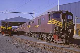
The South African Class 6E1, Series 10 of 1982 is a South African electric locomotive from the South African Railways era.
Between 1982 and 1984 the South African Railways placed fifty-five Class 6E1, Series 10 electric locomotives with a Bo-Bo wheel arrangement in service.[1]
Manufacturer
The 3 kV DC Class 6E1, Series 10 electric locomotive was designed and built for the South African Railways (SAR) by Union Carriage & Wagon (UCW) in Nigel, Transvaal, with the electrical equipment supplied by the General Electric Company (GEC).[2]
Fifty-five locomotives were delivered between 1982 and 1984, numbered in the range from E2086 to E2140. UCW did not allocate builder’s numbers to the locomotives it built for the SAR, but used the SAR unit numbers for their record keeping.[1]
Characteristics
Bogies
The Class 6E1 was built with sophisticated traction linkages on their bogies and with stabilisers mounted between the linkages on the bogies and the locomotive body. Together with its electronic wheelslip detection system, these traction linkages and stabilisers ensured the maximum transfer of power to the rails without causing wheelslip.[3]
Orientation
These dual cab locomotives have a roof access ladder on one side only, just to the right of the cab access door. The roof access ladder end is marked as the number 2 end. A passage along the centre of the locomotive connects the cabs, which are identical apart from the fact that the handbrake is located in cab 2. A pantograph hook stick is stowed in a tube mounted below the lower edge of the locomotive body on the roof access ladder side. The locomotive has three small panels along the lower half of the body and a large hatch door below the second small window to the right of the side door on the roof access ladder side, and only one small panel and a large hatch door below the first window immediately to the right of the door on the opposite side.[1]
Series identifying features
The Class 6E1 was produced in eleven series over a period of nearly sixteen years. While some of the Class 6E1 series are visually indistinguishable from their predecessors or successors, some externally visible changes did occur over the years. Series 1 locomotives had their sandboxes mounted on the bogies, while Series 2 to 11 locomotives had their sandboxes mounted along the bottom edge of the locomotive body, with the sandbox lids fitting into recesses in the body.[1]
Series 8 and later locomotives could be distinguished from all older models by the large hatch door on each side, below the second small window to the right of the side door on the roof access ladder side, and below the first window immediately to the right of the door on the other side.[1][3]
The Series 9 to Series 11 locomotives were visually indistinguishable from each other, but could be distinguished from all earlier models by the rainwater drainage holes on their lower sides. These holes were usually covered by so-called buckets, but the covers were absent on a few locomotives. Another distinction was the end doors that were recessed into the doorframes on Series 9 to Series 11 locomotives, compared to earlier models that had their end doors flush with the doorframes. In addition, on Series 9 and later the split side window on the driver’s assistant side was replaced by a single rectangular side window with rounded corners. Finally, unlike all earlier models, all four doors on Series 9 to Series 11 locomotives had rounded corners.[4]
Crew access
The Class 5E, 5E1, 6E and earlier 6E1 locomotives are notoriously difficult to enter from ground level since their lever-style door handles are at waist level when standing inside the locomotive, making it impossible to open the door from outside without first climbing up high enough to reach the door handle while hanging on to the side handrails with one hand only. Crews therefore often chose to leave the doors ajar when parking and exiting the locomotives.[5]
Side doors with two interconnected latch handles on the outside, such as those that were introduced on the Class 7E1, with one outside handle mounted near floor level and the other at mid-door level, were also introduced on Class 6E1 locomotives beginning with Series 9.[6]
Operation
Startup
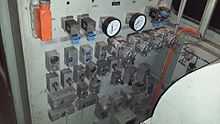
When there is no compressed air in the locomotive's system to raise a pantograph to start up, a pantograph hook stick is used to manually raise the pantograph. This starts the high voltage motor that drives the auxiliary alternator to supply 110V power to start the compressor and power other control circuits. Once there is enough main air pressure to keep the pantograph in the raised position, the pantograph hook stick can be dropped.[7]
The locomotive is controlled via resistors over which the voltage is dropped in a configuration of series and parallel electrical circuits. The circuit breakers that switch these circuits work under very high power and voltage and are therefore all pneumatically operated for insulation purposes. Compressed air is required to open or close the switch actions and air is also used for the weakfield cam switch, which also switches under very high currents.[7]
Running
Upon starting off and in the low notches the major part of the voltage is dropped over the banks of resistors and all four traction motors are in series.[7] The blowers that accelerate the dissipation of heat in the resistor banks give the Class 6E1 its very distinctive sound, a deep and loud whine when power is applied.[8]
As the driver notches up, some of the resistor banks are cut out via the pneumatically operated switches and the voltage increases across the traction motors. The more resistors that are cut out as the driver notches higher, the more power is developed by the traction motors. At around 22 to 28 kilometres per hour (14 to 17 miles per hour) the locomotive switches to a parallel combination, where the two traction motors per bogie are in a series electrical circuit while the two bogies are in parallel electrical circuit. Eventually, when all resistors are cut out, the locomotive is operating in full-field.[7]
When the traction motors are operated in full-field, be it in series or parallel mode, they are performing at maximum power for normal operation. To increase the speed at this point, if necessary, higher power output is required from the traction motors. The only way to increase power is to force a higher current flow over short periods. To accomplish this, the weakfield cam switch switches resistance in parallel with the field coils, which reduces the overall resistance of the field coils. This increases the magnetic flux and more power is generated by the traction motors.[7]
Brakes
The locomotive itself used air brakes, but it was equipped to operate trains with air or vacuum brakes. The brake system would be set up for either air or vacuum train working by means of a turning switch on the driver's brake valve and by pre-setting the appropriate brake valves in the passage.
While hauling a vacuum braked train, the locomotive's air brake system would be disabled and the train would be controlled using the train brakes alone to slow down and stop. While hauling an air braked train, on the other hand, the locomotive brakes would engage along with the train brakes. While working either type of train downgrade, the locomotive's regenerative braking system would also work in conjunction with the train brakes.
When the locomotive was stopped, the air brakes on both bogies were applied together. The handbrake or parking brake, located in Cab no. 2, only operated on the unit's last axle, or no. 7 and 8 wheels.
Service
The Class 6E1 family saw service all over both of the 3 kV DC mainline and branchline networks, the smaller Cape Western network between Cape Town and Beaufort West and the larger network that covers portions of the Northern Cape, the Free State, Natal, Gauteng, North West Province and Mpumalanga.[9]
Rebuilding to Class 18E

Beginning in 2000, Spoornet began a project to rebuild Series 2 to 11 Class 6E1 locomotives to Class 18E, Series 1 and Series 2 at the Transnet Rail Engineering (TRE) workshops at Koedoespoort. In the process the cab at the number 1 end was stripped of all controls and the driver's front and side windows were blanked off in order to have a toilet installed, thereby forfeiting the locomotive's bi-directional ability.[9][10]
Since the driving cab's noise level had to be below 85 decibels, cab 2 was selected as the Class 18E driving cab primarily based on its lower noise level compared to cab 1, which is closer and more exposed to the compressor's noise and vibration. Another factor was the closer proximity of cab 2 to the low voltage switch panel. The fact that the handbrake was located in cab 2 was not a deciding factor, but was considered an additional benefit.[10]
While the earlier Class 6E1, Series 2 to 7 locomotives had been built with a brake system consisting of various valves connected to each other with pipes, commonly referred to as a “bicycle frame” brake system, the Class 6E1, Series 8 to 11 locomotives were built with an air equipment frame brake system, commonly referred to as a brake rack. Since the design of the rebuilt Class 18E locomotives included the same brake rack, the rebuilding project was begun with the newer series 8 to 11 locomotives in order to reduce the overall cost of rebuilding.[10]
By June 2005 all Series 10 locomotives except numbers E2111 and E2134 were rebuilt to Class 18E, Series 1. The fate of the two exceptions is not known and they are presumed to have been scrapped. Their numbers and renumbering details are shown in the table.[9][10]
Count |
6E1 no. |
Year built |
18E no. |
18E series |
Year rebuilt |
Notes |
|---|---|---|---|---|---|---|
| 1 | E2086 | 1982 | 18-158 | 1 | 2004 | |
| 2 | E2087 | 1982 | 18-046 | 1 | 2002 | |
| 3 | E2088 | 1982 | 18-089 | 1 | 2003 | |
| 4 | E2089 | 1983 | 18-023 | 1 | 2002 | |
| 5 | E2090 | 1983 | 18-130 | 1 | 2004 | |
| 6 | E2091 | 1983 | 18-176 | 1 | 2004 | |
| 7 | E2092 | 1983 | 18-164 | 1 | 2005 | |
| 8 | E2093 | 1983 | 18-059 | 1 | 2002 | |
| 9 | E2094 | 1983 | 18-126 | 1 | 2004 | |
| 10 | E2095 | 1983 | 18-039 | 1 | 2002 | |
| 11 | E2096 | 1983 | 18-174 | 1 | 2004 | |
| 12 | E2097 | 1983 | 18-180 | 1 | 2005 | |
| 13 | E2098 | 1983 | 18-179 | 1 | 2005 | |
| 14 | E2099 | 1983 | 18-053 | 1 | 2002 | |
| 15 | E2100 | 1983 | 18-149 | 1 | 2004 | |
| 16 | E2101 | 1983 | 18-166 | 1 | 2003 | |
| 17 | E2102 | 1983 | 18-044 | 1 | 2002 | |
| 18 | E2103 | 1983 | 18-175 | 1 | 2004 | |
| 19 | E2104 | 1983 | 18-160 | 1 | 2005 | |
| 20 | E2105 | 1983 | 18-102 | 1 | 2003 | |
| 21 | E2106 | 1983 | 18-004 | 1 | 2001 | |
| 22 | E2107 | 1983 | 18-186 | 1 | 2005 | |
| 23 | E2108 | 1983 | 18-177 | 1 | 2004 | |
| 24 | E2109 | 1983 | 18-081 | 1 | 2003 | |
| 25 | E2110 | 1983 | 18-052 | 1 | 2002 | |
| 26 | E2112 | 1983 | 18-060 | 1 | 2002 | |
| 27 | E2113 | 1983 | 18-151 | 1 | 2004 | |
| 28 | E2114 | 1983 | 18-108 | 1 | 2004 | |
| 29 | E2115 | 1983 | 18-191 | 1 | 2005 | |
| 30 | E2116 | 1983 | 18-099 | 1 | 2003 | |
| 31 | E2117 | 1983 | 18-155 | 1 | 2004 | |
| 32 | E2118 | 1983 | 18-096 | 1 | 2003 | |
| 33 | E2119 | 1983 | 18-024 | 1 | 2002 | |
| 34 | E2120 | 1983 | 18-122 | 1 | 2004 | |
| 35 | E2121 | 1983 | 18-113 | 1 | 2004 | |
| 36 | E2122 | 1983 | 18-085 | 1 | 2003 | |
| 37 | E2123 | 1983 | 18-103 | 1 | 2003 | |
| 38 | E2124 | 1983 | 18-076 | 1 | 2003 | |
| 39 | E2125 | 1983 | 18-016 | 1 | 2002 | |
| 40 | E2126 | 1984 | 18-082 | 1 | 2003 | |
| 41 | E2127 | 1984 | 18-131 | 1 | 2004 | |
| 42 | E2128 | 1984 | 18-032 | 1 | 2002 | |
| 43 | E2129 | 1984 | 18-043 | 1 | 2002 | |
| 44 | E2130 | 1984 | 18-121 | 1 | 2004 | |
| 45 | E2131 | 1984 | 18-040 | 1 | 2002 | |
| 46 | E2132 | 1984 | 18-047 | 1 | 2002 | |
| 47 | E2133 | 1984 | 18-123 | 1 | 2004 | |
| 48 | E2135 | 1984 | 18-114 | 1 | 2004 | |
| 49 | E2136 | 1984 | 18-132 | 1 | 2004 | |
| 50 | E2137 | 1984 | 18-115 | 1 | 2004 | |
| 51 | E2138 | 1984 | 18-088 | 1 | 2003 | |
| 52 | E2139 | 1984 | 18-128 | 1 | 2004 | |
| 53 | E2140 | 1984 | 18-153 | 1 | 2004 | |
See also
- Electric locomotive numbering and classification
- List of South African locomotive classes
- South African Class 6E1, Series 1
- South African Class 6E1, Series 2
- South African Class 6E1, Series 3
- South African Class 6E1, Series 4
- South African Class 6E1, Series 5
- South African Class 6E1, Series 6
- South African Class 6E1, Series 7
- South African Class 6E1, Series 8
- South African Class 6E1, Series 9
- South African Class 6E1, Series 11
- South African Class 18E, Series 1
- South African locomotive history
References
|
- ↑ 1.0 1.1 1.2 1.3 1.4 1.5 South African Railways Index and Diagrams Electric and Diesel Locomotives, 610mm and 1065mm Gauges, Ref LXD 14/1/100/20, 28 January 1975, as amended
- ↑ "UCW - Electric locomotives" (PDF). The UCW Partnership. Archived from the original (PDF) on 12 October 2007. Retrieved 30 September 2010.
- ↑ 3.0 3.1 Paxton, Leith; Bourne, David (1985). Locomotives of the South African Railways (1st ed.). Cape Town: Struik. pp. 128–129. ISBN 0869772112.
- ↑ 18-050 (ex Series 9 E2013) with recessed end door and rounded door corners
- ↑ E1882 with high mounted door handle
- ↑ 18-253 (ex Series 9 E2058) with two door handles
- ↑ 7.0 7.1 7.2 7.3 7.4 Operation - South African Classes 6E, 6E1, 16E, 17E and 18E
- ↑ Dulez, Jean A. (2012). Railways of Southern Africa 150 Years (Commemorating One Hundred and Fifty Years of Railways on the Sub-Continent - Complete Motive Power Classifications and Famous Trains - 1860-2011) (1st ed.). Garden View, Johannesburg, South Africa: Vidrail Productions. p. 297. ISBN 9 780620 512282.
- ↑ 9.0 9.1 9.2 Railways of Southern Africa Locomotive Guide, 2002 Edition, (Compiled by John N. Middleton), p57, as amended by Combined Amendment List 4, January 2009
- ↑ 10.0 10.1 10.2 10.3 Information gathered from the rebuild files of individual locomotives at Transnet Rail Engineering’s Koedoespoort shops, or obtained from John Middleton as well as several Transnet employees