South African Class 18E, Series 1
| South African Class 18E, Series 1 | |
|---|---|
|
No. 18-224 at Ladysmith, KwaZulu-Natal, 5 August 2007 | |
| Type and origin | |
| Power type | Electric |
| Designer | Union Carriage and Wagon |
| Builder | Union Carriage and Wagon |
| Model | UCW 6E1 Series 6 to 11 |
| Build date | 1976-1985 |
| Total produced | 540 Series 6 to 11 |
| Rebuilder |
Transwerk Transnet Rail Engineering |
| Rebuild date | 2000-2009[1] |
| Number rebuilt | 446 |
| Specifications | |
| UIC classification | Bo-Bo |
| Gauge | 3 ft 6 in (1,067 mm) Cape gauge |
| Bogies | 3.43 m (11 ft 3 in) wheelbase |
| Wheel diameter | 1,220 mm (48 in) |
| Wheelbase | 11.279 m (37 ft 0.1 in) |
| Length | 15.494 m (50 ft 10 in) |
| Width | 2.896 m (9 ft 6 in) |
| Height | 4.089 m (13 ft 5 in) pantographs down |
| Axle load | 22,226 kg (21.9 long tons) |
| Locomotive weight | 88,904 kg (87.5 long tons) permissible |
| Current collection method | Pantographs[2] |
| Performance figures | |
| Locomotive brake | Air & Rheostatic |
| Train brakes | Air & Vacuum |
| Career | |
| Operator(s) |
Spoornet Transnet Freight Rail PRASA |
| Class | Class 18E |
| Power class | 3 kV DC |
| Number in class | 446[1] |
| Number(s) |
18-001 to 18-420 18-500 to 18-525 |
| Delivered | 2000-2009 |
| First run | 2000 |
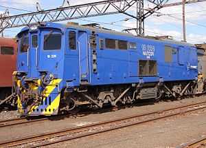
The South African Class 18E, Series 1 of 2000 is a South African electric locomotive from the Spoornet era.
Beginning in 2000 Spoornet embarked on a program to rebuild Class 6E1 locomotives to Class 18E, Series 1 locomotives. Most of the Class 6E1s that had previously been reclassified or modified to Class 16E or Class 17E respectively were rebuilt to Class 18E as well.[3]
Manufacturer
The 3 kV DC Class 6E1 electric locomotive was built for the South African Railways (SAR) by Union Carriage and Wagon (UCW) in Nigel, Transvaal, with the electrical equipment supplied by the General Electric Company (GEC). Eleven series of Class 6E1 were delivered between 1969 and 1984, with altogether nine hundred and sixty units built. UCW did not allocate builder’s numbers to the locomotives it built for the SAR, but used the SAR unit numbers for their record keeping.[4]
Rebuilding
The rebuilding to Class 18E, Series 1 was done by Transwerk, later renamed Transnet Rail Engineering (TRE) and then Transnet Engineering (TE), at its Koedoespoort workshops in Pretoria. The rebuilding to Series 1 locomotives ceased in 2009 with 446 units rebuilt from Class 6E1, Series 6 to 11 locomotives, numbered in the ranges from 18-001 to 18-420 and 18-500 to 18-525.[3]
Since it was probably not intended at the beginning of the project to rebuild virtually the whole fleet of Class 6E1s to Class 18Es, most of the early rebuildings were done on the newest of the Class 6E1 fleet, Series 8 to 11. One of the reasons was that these series, numbers E1896 and up, already had an air equipment frame brake system, commonly referred to as a brake rack, similar to that intended for the Class 18E, which would reduce the overall per unit cost of rebuilding.[5] Another consideration was possibly that their bodywork usually required less heavy repairs than the older models in terms of rust and other damage such as bent panels and frames.[1]
Similar considerations possibly also applied when older Class 6E1s of Series 6 and 7 began to be rebuilt in 2003, since these units in the number range from E1646 to E1895 used the same brake valve as that of the Class 18E. The result by 2013, however, was a fleet of already ageing Class 18Es and ancient Class 6E1s, the latter mostly of Series 6 and older models.[1]
The Class 6E1 locomotives were built with an air brake system consisting of various valves connected to each other with pipes, commonly referred to as a “bicycle frame” brake system. The compressed air pipe is run through bolster and other members and then in a zig-zag pattern under the locomotive's belly to extend its length in order to allow the maximum amount of moisture to condense on the way to the reservoirs. As a result it has multiple pipe connections. A weakness of the system was that, after an accident or even a hard coupling, these pipes tended to develop leaks at the joints that were extremely difficult to repair.[5]
When Class 6E1, Series 7 and earlier locomotives began to be rebuilt, it was necessary to retrofit them with a brake equipment frame or brake rack. Since this already increased the per unit rebuilding cost, it was decided to simultaneously re-route the compressor pipe away from bolster and other members to the outside of the bodywork on the locomotive's right side, from below and to the right of the cab door to just before the second sandbox lid from the rear end. An added advantage was that the pipe would run cooler and more moisture would condense on the way to the reservoirs. The same modification was not done on locomotives that were rebuilt from Class 6E1, Series 8 and later.[5]
Features
Orientation
The Class 6E1 from which it was rebuilt is a dual cab locomotive and has a roof access ladder on one side only, just to the right of the cab access door. The roof access ladder end is marked as the number 2 end. A passage along the centre of the locomotive connects the cabs, which are identical apart from the fact that the handbrake is located in cab 2.[2]
The rebuilt Class 18E locomotive, on the other hand, is a single cab unit since cab 1 was stripped of all controls during the rebuilding, to have additional equipment and a chemical toilet installed. Since the driving cab's noise level had to be below 85 decibels, cab 2 was selected as the Class 18E driving cab primarily based on its lower noise level compared to cab 1, which is closer and more exposed to the compressor's noise and vibration. Another factor was the closer proximity of cab 2 to the low voltage switch panel. The fact that the handbrake was located in cab 2 was not a deciding factor, but was considered an additional benefit.[1][2][3][6]
Beginning in 2009, in an attempt to reduce theft, the 110V battery bank was relocated from the locomotive sides below the frame and between the bogies to cab 1, where the toilet occupied less than half of the available space. This appears to have been done only with numbers 18-510 and later. Identifying features are a small grille to the left of the cab 1 side door and, in most cases, the remaining battery box frames without side covers.[1]
Equipment
The rebuilding included the installation of Alsthom micro-processor control technology. New equipment in the totally refurbished Class 18E locomotive include the following:[3]
- A transducer to relay vacuum and compressed air pressure to an electric signal.
- Dual-purpose main resistance modules that replaced the accelerating resistance system and that are used for motoring and rheostatic braking. The resistance blowers use AC motors that are powered through inverters.[1]
- A DC current transformer (DCCT) that measures the current flowing to and from certain equipment such as the traction motors, or total overhead line current.
- A potential divider to measure the voltage in the overhead equipment and traction motors.
- A main processor unit (MPU), located in high tension compartment 1, used for primary (master) control of the locomotive.
- Remote input-output modules (RIOM) located in high tension compartment 2, in the low tension panel and the driving compartment, used for secondary (slave) control of the locomotive.
- Two digital display units (DDU) mounted on the driving console to display, for example, information like speed, current draw and available overhead voltage, current draw of the traction motors in each bogie, rheostatic braking current generated per bogie, as well as performance information about all the locomotives in the consisted set.[3]
- Overspeed protection that will automatically open the line switches if any pair of wheels slips and a speed of 95 kilometres per hour (59 miles per hour) is exceeded.[6]
- The driver's cab and console received a lot of attention to ensure crew comfort and safety. It included the installation of an air conditioner and windows that offer better protection against rocks thrown by trackside vagrants.[1]
All traction motors underwent a complete refurbishment and were tested back-to-back to ensure quality.[1]
Locomotive brakes
The Class 6E1 locomotives were equipped with regenerative brakes. With regenerative braking the energy generated by the traction motors is dissipated by the resistor grid banks at the substations when it is not absorbed by other locomotives in the same electrical section. A stumbling block was that the regeneration equipment at many of the sub-stations along the route was unreliable and since there was no guarantee that another train would be in the same section to absorb the regenerated energy, there was always the risk that line voltage could exceed 4.1 kV, which would make either the sub-station or the locomotive trip out.[7]
As a result the rebuilt Class 18E locomotives were equipped with rheostatic braking instead of regenerative braking. With rheostatic braking the energy generated by the traction motors is dissipated by the resistor grids on the locomotive itself. The rheostatic braking of the Class 18E was superior and very reliable for higher speed trains when compared with the regenerative braking of the older Classes 6E1 and 17E locomotives.[7]
Operation
The locomotive is controlled via resistors over which the voltage is dropped in a configuration of series and parallel electrical circuits. The circuit breakers that switch these circuits work under very high power and voltage and are all pneumatically operated for insulation purposes. Compressed air is required to open or close the switch actions and air is also used for the weak field cam switch that also switches under very high currents.[7]
Upon starting off and in the low notches the major part of the voltage is dropped over the banks of resistors and all four traction motors are in series. As the driver notches up, some of the resistor banks are cut out via the pneumatically operated switches and the voltage increases across the traction motors. The more resistors that are cut out as the driver notches higher, the more power is developed by the traction motors. At around 22 to 28 kilometres per hour (14 to 17 miles per hour) the locomotive switches to a parallel combination, where the two traction motors per bogie are in a series electrical circuit while the two bogies are in parallel electrical circuit. Eventually, when all resistors are cut out, the locomotive is operating in full-field.[7]
The locomotives in a consisted set are switched between series and parallel mode automatically, based on speed, overhead voltage and electromotive force (EMF). The driver can select "series hold" to force some or all of the locomotives in the consisted set to remain in series mode when overhead voltage is low. If nothing is done, some of the locomotives will switch off under low overhead voltage conditions to prevent damage to resistors and switch on again when the voltage improves.[1][7]
Identifying features
The most obvious visual feature to distinguish the Class 18E from the Class 6E1 is the filled in driver’s windows at the rear end where the toilet is installed. On the first rebuilds, as observed up to number 18-012, the small driver’s side window was left in place as a toilet window, but most of these have since also been filled in. The remaining rear windscreen still has the slanted upper edge of the 6E1 windscreens, but the new front windscreens on the Class 18E are rectangular.[6]
On the sides, obvious visual distinctions from the Class 6E1 are the left one of the two large grilles that was removed, with the opening filled in, two new large grilles that are installed in the centre lower sides to serve as air intakes for the rheostatic braking resistance blowers, and a large access door to one of the high-tension compartments that is installed in place of the rightmost small window that was in the upper side of the Class 6E1. On some Class 18E locomotives one or more of the remaining small windows were slightly enlarged vertically. On the left side, the air intakes for the air conditioner in the cab are installed between the top three steps of the roof access ladder.[6]
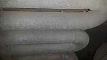
Locomotives rebuilt from Class 6E1, Series 6 and 7 have part of the compressed air piping sunk into a recess that runs along the rear of the lower edge of the body on the locomotive’s right side, the side opposite the roof access ladder side. On locomotives rebuilt from Class 6E1, Series 8 to 11 this pipe was not rerouted.
Lineage identification
All features that distinguished Class 6E1, Series 6 to 11 locomotives from each other are still present on the Class 18E rebuilds, making it possible to visually determine the Class 6E1 origin of Class 18E locomotives. Examples are shown in the pictures below.[2]
- The smooth sides of ex Series 6 and 7 locomotives and, on the Class 18Es rebuilt from them, the recessed compressed air pipe on the right side.
- The rainwater beading above the small grilles immediately to the right of the side door, that was only installed on Series 6 and later Class 6E1s.
- The large hatch door on each side, below the second small window to the right of the side door on the roof access ladder side, and below the first window immediately to the right of the door on the opposite side, on ex Series 8 to 11 locomotives.
- The rain water downpipe drainage holes on the lower sides of ex Series 9 to 11 locomotives. As on the pre-rebuilt locomotives, these holes are usually covered by so-called buckets, but these covers are absent on several units.
- The end doors that are flush with the doorframes on ex Series 6 to 8 locomotives, and recessed into the doorframes on ex Series 9 to 11 locomotives;
- The small side windows on the driver’s assistant’s side that was omitted on ex Series 9 to 11 locomotives;
- The squared corners on all doors on ex Series 6 to 8 locomotives, with a weather strip at the bottom, and the rounded corners and no weather strips on all doors on ex Series 9 to 11 locomotives;
- The side doors with:
- mid door mounted door handles on ex Series 6 and early Series 7 locomotives;
- low mounted handles with a mid door drawer pull type handle at mid-door level on ex later Series 7 and Series 8 locomotives; and
- two interconnected latch handles on the outside, one handle mounted near floor level and the other at mid door level, on ex Class 6E1 Series 9 to 11 locomotives.
Table of rebuilds
The table shows the original Class 6E1 number, series and year built for each Class 18E, Series 1 locomotive, as well as the year it was rebuilt to Class 18E. All the table columns are sortable.[1][3]
Count |
6E1 no. |
6E1 ser. |
Year built |
18E no. |
Year rebuilt |
Notes |
|---|---|---|---|---|---|---|
| 1 | E1954 | 8 | 1980 | 18-001 | 2000 | |
| 2 | E1955 | 8 | 1980 | 18-002 | 2001 | |
| 3 | E2150 | 11 | 1984 | 18-003 | 2001 | |
| 4 | E2106 | 10 | 1983 | 18-004 | 2001 | |
| 5 | E2144 | 11 | 1984 | 18-005 | 2001 | |
| 6 | E1920 | 8 | 1979-80 | 18-006 | 2001 | |
| 7 | E2166 | 11 | 1985 | 18-007 | 2001 | |
| 8 | E2074 | 9 | 1982 | 18-008 | 2001 | |
| 9 | E2004 | 9 | 1981-82 | 18-009 | 2001 | |
| 10 | E1912 | 8 | 1979 | 18-010 | 2001 | |
| 11 | E1942 | 8 | 1980 | 18-011 | 2001 | |
| 12 | E1911 | 8 | 1979 | 18-012 | 2001 | |
| 13 | E1978 | 8 | 1980 | 18-013 | 2001 | |
| 14 | E1975 | 8 | 1980 | 18-014 | 2002 | |
| 15 | E1961 | 8 | 1980 | 18-015 | 2002 | |
| 16 | E2125 | 10 | 1983 | 18-016 | 2002 | |
| 17 | E2167 | 11 | 1985 | 18-017 | 2002 | |
| 18 | E1935 | 8 | 1980 | 18-018 | 2002 | ex 17E |
| 19 | E1974 | 8 | 1980 | 18-019 | 2002 | |
| 20 | E2072 | 9 | 1982 | 18-020 | 2002 | |
| 21 | E1902 | 8 | 1979 | 18-021 | 2002 | |
| 22 | E2010 | 9 | 1981-82 | 18-022 | 2002 | |
| 23 | E2089 | 10 | 1983 | 18-023 | 2002 | |
| 24 | E2119 | 10 | 1983 | 18-024 | 2002 | |
| 25 | E1903 | 8 | 1979 | 18-025 | 2002 | |
| 26 | E1980 | 8 | 1980 | 18-026 | 2002 | |
| 27 | E1981 | 8 | 1980 | 18-027 | 2002 | |
| 28 | E2055 | 9 | 1982 | 18-028 | 2002 | ex 17E |
| 29 | E2001 | 9 | 1981 | 18-029 | 2002 | ex 16-500A |
| 30 | E2002 | 9 | 1981 | 18-030 | 2002 | ex 16-500B |
| 31 | E2157 | 11 | 1984 | 18-031 | 2002 | |
| 32 | E2128 | 10 | 1984 | 18-032 | 2002 | |
| 33 | E1925 | 8 | 1979-80 | 18-033 | 2002 | ex 16-504A |
| 34 | E1926 | 8 | 1979-80 | 18-034 | 2002 | ex 16-504B |
| 35 | E1916 | 8 | 1979-80 | 18-035 | 2002 | ex 16-501A |
| 36 | E1917 | 8 | 1979-80 | 18-036 | 2002 | ex 16-501B |
| 37 | E2037 | 9 | 1981-82 | 18-037 | 2002 | ex 17E |
| 38 | E2165 | 11 | 1985 | 18-038 | 2002 | |
| 39 | E2095 | 10 | 1983 | 18-039 | 2002 | |
| 40 | E2131 | 10 | 1984 | 18-040 | 2002 | |
| 41 | E1988 | 8 | 1981 | 18-041 | 2002 | |
| 42 | E2009 | 9 | 1981-82 | 18-042 | 2002 | |
| 43 | E2129 | 10 | 1984 | 18-043 | 2002 | |
| 44 | E2102 | 10 | 1983 | 18-044 | 2002 | |
| 45 | E2021 | 9 | 1981-82 | 18-045 | 2002 | |
| 46 | E2087 | 10 | 1982 | 18-046 | 2002 | |
| 47 | E2132 | 10 | 1984 | 18-047 | 2002 | |
| 48 | E2180 | 11 | 1985 | 18-048 | 2002 | |
| 49 | E1929 | 8 | 1979-80 | 18-049 | 2002 | ex 16-506B |
| 50 | E2013 | 9 | 1981-82 | 18-050 | 2002 | |
| 51 | E1963 | 8 | 1980 | 18-051 | 2002 | |
| 52 | E2110 | 10 | 1983 | 18-052 | 2002 | |
| 53 | E2099 | 10 | 1983 | 18-053 | 2002 | |
| 54 | E2078 | 9 | 1982 | 18-054 | 2002 | |
| 55 | E1928 | 8 | 1979-80 | 18-055 | 2002 | ex 16-506A |
| 56 | E2061 | 9 | 1982 | 18-056 | 2002 | |
| 57 | E2083 | 9 | 1982 | 18-057 | 2002 | |
| 58 | E2014 | 9 | 1981-82 | 18-058 | 2002 | |
| 59 | E2093 | 10 | 1983 | 18-059 | 2002 | |
| 60 | E2112 | 10 | 1983 | 18-060 | 2002 | |
| 61 | E1909 | 8 | 1979 | 18-061 | 2002 | ex 17E |
| 62 | E1946 | 8 | 1980 | 18-062 | 2002 | ex 17E |
| 63 | E1918 | 8 | 1979-80 | 18-063 | 2002 | ex 16-505A |
| 64 | E1949 | 8 | 1980 | 18-064 | 2002 | ex 17E |
| 65 | E1999 | 8 | 1981 | 18-065 | 2002 | ex 17E |
| 66 | E2183 | 11 | 1985 | 18-066 | 2003 | |
| 67 | E1919 | 8 | 1979-80 | 18-067 | 2003 | ex 16-505B |
| 68 | E2149 | 11 | 1984 | 18-068 | 2002 | |
| 69 | E1948 | 8 | 1980 | 18-069 | 2003 | |
| 70 | E1962 | 8 | 1980 | 18-070 | 2003 | ex 17E |
| 71 | E2162 | 11 | 1984 | 18-071 | 2003 | |
| 72 | E1958 | 8 | 1980 | 18-072 | 2003 | |
| 73 | E2075 | 9 | 1982 | 18-073 | 2003 | ex 17E |
| 74 | E2038 | 9 | 1981-82 | 18-074 | 2003 | ex 17E |
| 75 | E2153 | 11 | 1984 | 18-075 | 2003 | |
| 76 | E2124 | 10 | 1983 | 18-076 | 2003 | |
| 77 | E1914 | 8 | 1979 | 18-077 | 2003 | ex 16-503A |
| 78 | E1915 | 8 | 1979 | 18-078 | 2003 | ex 16-503B |
| 79 | E2056 | 9 | 1982 | 18-079 | 2003 | ex 17E |
| 80 | E1885 | 7 | 1979 | 18-080 | 2003 | |
| 81 | E2109 | 10 | 1983 | 18-081 | 2003 | |
| 82 | E2126 | 10 | 1984 | 18-082 | 2003 | |
| 83 | E2184 | 11 | 1985 | 18-083 | 2003 | |
| 84 | E1940 | 8 | 1980 | 18-084 | 2003 | ex 17E |
| 85 | E2122 | 10 | 1983 | 18-085 | 2003 | |
| 86 | E1831 | 7 | 1978 | 18-086 | 2003 | |
| 87 | E1904 | 8 | 1979 | 18-087 | 2003 | ex 17E |
| 88 | E2138 | 10 | 1984 | 18-088 | 2003 | |
| 89 | E2088 | 10 | 1982 | 18-089 | 2003 | |
| 90 | E1871 | 7 | 1978-79 | 18-090 | 2003 | |
| 91 | E2152 | 11 | 1984 | 18-091 | 2003 | |
| 92 | E2154 | 11 | 1984 | 18-092 | 2003 | |
| 93 | E2053 | 9 | 1982 | 18-093 | 2003 | ex 17E |
| 94 | E1934 | 8 | 1980 | 18-094 | 2003 | ex 17E |
| 95 | E2163 | 11 | 1984 | 18-095 | 2003 | |
| 96 | E2118 | 10 | 1983 | 18-096 | 2003 | |
| 97 | E1822 | 7 | 1977-78 | 18-097 | 2003 | ex 17E |
| 98 | E2175 | 11 | 1985 | 18-098 | 2003 | |
| 99 | E2116 | 10 | 1983 | 18-099 | 2003 | |
| 100 | E1669 | 6 | 1976 | 18-100 | 2003 | ex 16-422A |
| 101 | E2158 | 11 | 1984 | 18-101 | 2003 | |
| 102 | E2105 | 10 | 1983 | 18-102 | 2003 | |
| 103 | E2123 | 10 | 1983 | 18-103 | 2003 | |
| 104 | E1686 | 6 | 1976 | 18-104 | 2003 | |
| 105 | E2155 | 11 | 1984 | 18-105 | 2003 | |
| 106 | E2174 | 11 | 1985 | 18-106 | 2003 | |
| 107 | E1780 | 7 | 1977 | 18-107 | 2003 | |
| 108 | E2114 | 10 | 1983 | 18-108 | 2004 | |
| 109 | E2173 | 11 | 1985 | 18-109 | 2004 | |
| 110 | E2170 | 11 | 1985 | 18-110 | 2004 | |
| 111 | E2142 | 11 | 1984 | 18-111 | 2004 | |
| 112 | E2164 | 11 | 1984 | 18-112 | 2004 | |
| 113 | E2121 | 10 | 1983 | 18-113 | 2004 | |
| 114 | E2135 | 10 | 1984 | 18-114 | 2004 | |
| 115 | E2137 | 10 | 1984 | 18-115 | 2004 | |
| 116 | E2146 | 11 | 1984 | 18-116 | 2004 | |
| 117 | E2141 | 11 | 1984 | 18-117 | 2004 | |
| 118 | E2182 | 11 | 1985 | 18-118 | 2004 | |
| 119 | E2151 | 11 | 1984 | 18-119 | 2004 | |
| 120 | E2176 | 11 | 1985 | 18-120 | 2004 | |
| 121 | E2130 | 10 | 1984 | 18-121 | 2004 | |
| 122 | E2120 | 10 | 1983 | 18-122 | 2004 | |
| 123 | E2133 | 10 | 1984 | 18-123 | 2004 | |
| 124 | E1687 | 6 | 1976 | 18-124 | 2004 | |
| 125 | E2156 | 11 | 1984 | 18-125 | 2004 | |
| 126 | E2094 | 10 | 1983 | 18-126 | 2004 | |
| 127 | E2079 | 9 | 1982 | 18-127 | 2004 | ex 17E |
| 128 | E2139 | 10 | 1984 | 18-128 | 2004 | |
| 129 | E2172 | 11 | 1985 | 18-129 | 2004 | |
| 130 | E2090 | 10 | 1983 | 18-130 | 2004 | |
| 131 | E2127 | 10 | 1984 | 18-131 | 2004 | |
| 132 | E2136 | 10 | 1984 | 18-132 | 2004 | |
| 133 | E1854 | 7 | 1978 | 18-133 | 2004 | |
| 134 | E1765 | 7 | 1977 | 18-134 | 2004 | |
| 135 | E1842 | 7 | 1978 | 18-135 | 2004 | |
| 136 | E2147 | 11 | 1984 | 18-136 | 2004 | |
| 137 | E1782 | 7 | 1977 | 18-137 | 2004 | |
| 138 | E1860 | 7 | 1978 | 18-138 | 2004 | |
| 139 | E1769 | 7 | 1977 | 18-139 | 2004 | |
| 140 | E2178 | 11 | 1985 | 18-140 | 2004 | |
| 141 | E1747 | 7 | 1977 | 18-141 | 2004 | |
| 142 | E1646 | 6 | 1976 | 18-142 | 2004 | |
| 143 | E1693 | 6 | 1976 | 18-143 | 2004 | |
| 144 | E1710 | 6 | 1976-77 | 18-144 | 2004 | |
| 145 | E2148 | 11 | 1984 | 18-145 | 2004 | |
| 146 | E2185 | 11 | 1985 | 18-146 | 2004 | |
| 147 | E1673 | 6 | 1976 | 18-147 | 2004 | |
| 148 | E2145 | 11 | 1984 | 18-148 | 2004 | |
| 149 | E2100 | 10 | 1983 | 18-149 | 2004 | |
| 150 | E2160 | 11 | 1984 | 18-150 | 2004 | |
| 151 | E2113 | 10 | 1983 | 18-151 | 2004 | |
| 152 | E2161 | 11 | 1984 | 18-152 | 2004 | |
| 153 | E2140 | 10 | 1984 | 18-153 | 2004 | |
| 154 | E2143 | 11 | 1984 | 18-154 | 2004 | |
| 155 | E2117 | 10 | 1983 | 18-155 | 2004 | |
| 156 | E1997 | 8 | 1981 | 18-156 | 2004 | ex 17E |
| 157 | E2181 | 11 | 1985 | 18-157 | 2004 | |
| 158 | E2086 | 10 | 1982 | 18-158 | 2004 | |
| 159 | E1746 | 7 | 1977 | 18-159 | 2004 | |
| 160 | E2104 | 10 | 1983 | 18-160 | 2005 | |
| 161 | E1893 | 7 | 1979 | 18-161 | 2005 | |
| 162 | E2159 | 11 | 1984 | 18-162 | 2005 | |
| 163 | E1742 | 6 | 1977 | 18-163 | 2005 | |
| 164 | E2092 | 10 | 1983 | 18-164 | 2005 | |
| 165 | E1785 | 7 | 1977 | 18-165 | 2003 | |
| 166 | E2101 | 10 | 1983 | 18-166 | 2003 | |
| 167 | E1699 | 6 | 1976-77 | 18-167 | 2004 | ex 16-425A |
| 168 | E2171 | 11 | 1985 | 18-168 | 2004 | |
| 169 | E1700 | 6 | 1976-77 | 18-169 | 2004 | ex 16-425B |
| 170 | E2179 | 11 | 1985 | 18-170 | 2005 | |
| 171 | E2168 | 11 | 1985 | 18-171 | 2005 | |
| 172 | E2177 | 11 | 1985 | 18-172 | 2005 | |
| 173 | E2169 | 11 | 1985 | 18-173 | 2005 | |
| 174 | E2096 | 10 | 1983 | 18-174 | 2004 | |
| 175 | E2103 | 10 | 1983 | 18-175 | 2004 | |
| 176 | E2091 | 10 | 1983 | 18-176 | 2004 | |
| 177 | E2108 | 10 | 1983 | 18-177 | 2004 | |
| 178 | E1966 | 8 | 1980 | 18-178 | 2005 | ex 17E |
| 179 | E2098 | 10 | 1983 | 18-179 | 2005 | |
| 180 | E2097 | 10 | 1983 | 18-180 | 2005 | |
| 181 | E2080 | 9 | 1982 | 18-181 | 2005 | |
| 182 | E1704 | 6 | 1976-77 | 18-182 | 2005 | |
| 183 | E1876 | 7 | 1979 | 18-183 | 2005 | |
| 184 | E1790 | 7 | 1977-78 | 18-184 | 2005 | ex 16-407B |
| 185 | E1730 | 6 | 1977 | 18-185 | 2005 | |
| 186 | E2107 | 10 | 1983 | 18-186 | 2005 | |
| 187 | E1788 | 7 | 1977-78 | 18-187 | 2005 | |
| 188 | E1796 | 7 | 1977-78 | 18-188 | 2005 | |
| 189 | E1697 | 6 | 1976-77 | 18-189 | 2005 | |
| 190 | E1656 | 6 | 1976 | 18-190 | 2005 | |
| 191 | E2115 | 10 | 1983 | 18-191 | 2005 | |
| 192 | E2065 | 9 | 1982 | 18-192 | 2005 | ex 17E |
| 193 | E2025 | 9 | 1981-82 | 18-193 | 2005 | ex 17E |
| 194 | E2020 | 9 | 1981-82 | 18-194 | 2005 | ex 17E |
| 195 | E1899 | 8 | 1979 | 18-195 | 2005 | |
| 196 | E2026 | 9 | 1981-82 | 18-196 | 2005 | ex 17E |
| 197 | E1944 | 8 | 1980 | 18-197 | 2005 | ex 17E |
| 198 | E1878 | 7 | 1979 | 18-198 | 2005 | |
| 199 | E1959 | 8 | 1980 | 18-199 | 2005 | |
| 200 | E1941 | 8 | 1980 | 18-200 | 2005 | |
| 201 | E1969 | 8 | 1980 | 18-201 | 2005 | ex 17E |
| 202 | E1931 | 8 | 1980 | 18-202 | 2005 | ex 17E |
| 203 | E1939 | 8 | 1980 | 18-203 | 2005 | ex 17E |
| 204 | E1972 | 8 | 1980 | 18-204 | 2005 | |
| 205 | E1894 | 7 | 1979 | 18-205 | 2005 | |
| 206 | E1750 | 7 | 1977 | 18-206 | 2005 | |
| 207 | E1945 | 8 | 1980 | 18-207 | 2005 | ex 17E |
| 208 | E1752 | 7 | 1977 | 18-208 | 2005 | |
| 209 | E1652 | 6 | 1976 | 18-209 | 2005 | |
| 210 | E2028 | 9 | 1981-82 | 18-210 | 2005 | ex 17E |
| 211 | E2022 | 9 | 1981-82 | 18-211 | 2005 | ex 17E |
| 212 | E2066 | 9 | 1982 | 18-212 | 2005 | ex 17E |
| 213 | E1873 | 7 | 1979 | 18-213 | 2005 | |
| 214 | E2085 | 9 | 1982 | 18-214 | 2005 | ex 17E |
| 215 | E1986 | 8 | 1980-81 | 18-215 | 2005 | ex 17E |
| 216 | E1937 | 8 | 1980 | 18-216 | 2005 | ex 17E |
| 217 | E2084 | 9 | 1982 | 18-217 | 2005 | ex 17E |
| 218 | E2052 | 9 | 1982 | 18-218 | 2005 | ex 17E |
| 219 | E2044 | 9 | 1982 | 18-219 | 2005 | ex 17E |
| 220 | E1960 | 8 | 1980 | 18-220 | 2005 | |
| 221 | E1932 | 8 | 1980 | 18-221 | 2005 | |
| 222 | E1968 | 8 | 1980 | 18-222 | 2005 | ex 17E |
| 223 | E2030 | 9 | 1981-82 | 18-223 | 2005 | ex 17E |
| 224 | E2070 | 9 | 1982 | 18-224 | 2005 | ex 17E |
| 225 | E1991 | 8 | 1981 | 18-225 | 2005 | ex 17E |
| 226 | E1984 | 8 | 1980-81 | 18-226 | 2005 | ex 17E |
| 227 | E2042 | 9 | 1981-82 | 18-227 | 2005 | ex 17E |
| 228 | E2076 | 9 | 1982 | 18-228 | 2005 | ex 17E |
| 229 | E2051 | 9 | 1982 | 18-229 | 2005 | ex 17E |
| 230 | E2039 | 9 | 1981-82 | 18-230 | 2005 | ex 17E |
| 231 | E1797 | 7 | 1977-78 | 18-231 | 2005 | |
| 232 | E2016 | 9 | 1981-82 | 18-232 | 2005 | ex 17E |
| 233 | E1837 | 7 | 1978 | 18-233 | 2005 | |
| 234 | E2043 | 9 | 1981-82 | 18-234 | 2005 | ex 17E |
| 235 | E2082 | 9 | 1982 | 18-235 | 2005 | ex 17E |
| 236 | E2007 | 9 | 1981-82 | 18-236 | 2005 | ex 17E |
| 237 | E1998 | 8 | 1981 | 18-237 | 2006 | ex 17E |
| 238 | E2045 | 9 | 1982 | 18-238 | 2005 | ex 17E |
| 239 | E2050 | 9 | 1982 | 18-239 | 2006 | ex 17E |
| 240 | E2057 | 9 | 1982 | 18-240 | 2005 | ex 17E |
| 241 | E2040 | 9 | 1981-82 | 18-241 | 2006 | ex 17E |
| 242 | E2063 | 9 | 1982 | 18-242 | 2006 | ex 17E |
| 243 | E2073 | 9 | 1982 | 18-243 | 2006 | ex 17E |
| 244 | E2077 | 9 | 1982 | 18-244 | 2006 | ex 17E |
| 245 | E2067 | 9 | 1982 | 18-245 | 2006 | ex 17E |
| 246 | E2033 | 9 | 1981-82 | 18-246 | 2006 | ex 17E |
| 247 | E2036 | 9 | 1981-82 | 18-247 | 2006 | ex 17E |
| 248 | E1943 | 8 | 1980 | 18-248 | 2006 | |
| 249 | E2018 | 9 | 1981-82 | 18-249 | 2006 | ex 17E |
| 250 | E2060 | 9 | 1982 | 18-250 | 2006 | ex 17E |
| 251 | E2081 | 9 | 1982 | 18-251 | 2006 | ex 17E |
| 252 | E2019 | 9 | 1981-82 | 18-252 | 2006 | ex 17E |
| 253 | E2058 | 9 | 1982 | 18-253 | 2006 | ex 17E |
| 254 | E2034 | 9 | 1981-82 | 18-254 | 2006 | ex 17E |
| 255 | E2011 | 9 | 1981-82 | 18-255 | 2006 | ex 17E |
| 256 | E1976 | 8 | 1980 | 18-256 | 2006 | ex 17E |
| 257 | E2054 | 9 | 1982 | 18-257 | 2006 | ex 17E |
| 258 | E2048 | 9 | 1982 | 18-258 | 2006 | ex 17E |
| 259 | E2024 | 9 | 1981-82 | 18-259 | 2006 | ex 17E |
| 260 | E1805 | 7 | 1977-78 | 18-260 | 2006 | ex 17E |
| 261 | E2015 | 9 | 1981-82 | 18-261 | 2006 | ex 17E |
| 262 | E1900 | 8 | 1979 | 18-262 | 2006 | ex 17E |
| 263 | E1967 | 8 | 1980 | 18-263 | 2006 | ex 17E |
| 264 | E1848 | 7 | 1978 | 18-264 | 2006 | ex 16-405A |
| 265 | E1849 | 7 | 1978 | 18-265 | 2006 | ex 16-405B |
| 266 | E1889 | 7 | 1979 | 18-266 | 2006 | |
| 267 | E2023 | 9 | 1981-82 | 18-267 | 2006 | ex 17E |
| 268 | E2047 | 9 | 1982 | 18-268 | 2006 | ex 17E |
| 269 | E1971 | 8 | 1980 | 18-269 | 2006 | ex 17E |
| 270 | E1843 | 7 | 1978 | 18-270 | 2006 | ex 17E |
| 271 | E2046 | 9 | 1982 | 18-271 | 2006 | ex 17E |
| 272 | E1982 | 8 | 1980 | 18-272 | 2006 | ex 17E |
| 273 | E2012 | 9 | 1981-82 | 18-273 | 2006 | ex 17E |
| 274 | E1936 | 8 | 1980 | 18-274 | 2006 | ex 17E |
| 275 | E2008 | 9 | 1981-82 | 18-275 | 2006 | ex 17E |
| 276 | E2041 | 9 | 1981-82 | 18-276 | 2006 | ex 17E |
| 277 | E1647 | 6 | 1976 | 18-277 | 2006 | |
| 278 | E1992 | 8 | 1981 | 18-278 | 2006 | ex 17E |
| 279 | E1995 | 8 | 1981 | 18-279 | 2006 | ex 17E |
| 280 | E1835 | 7 | 1978 | 18-280 | 2006 | |
| 281 | E2064 | 9 | 1982 | 18-281 | 2006 | ex 17E |
| 282 | E2062 | 9 | 1982 | 18-282 | 2006 | ex 17E |
| 283 | E1827 | 7 | 1977-78 | 18-283 | 2006 | ex 17E |
| 284 | E1906 | 8 | 1979 | 18-284 | 2006 | ex 17E |
| 285 | E2003 | 9 | 1981-82 | 18-285 | 2006 | ex 17E |
| 286 | E1923 | 8 | 1979-80 | 18-286 | 2006 | |
| 287 | E1694 | 6 | 1976 | 18-287 | 2006 | |
| 288 | E1908 | 8 | 1979 | 18-288 | 2006 | ex 17E |
| 289 | E1777 | 7 | 1977 | 18-289 | 2006 | ex 17E |
| 290 | E1947 | 8 | 1980 | 18-290 | 2006 | ex 17E |
| 291 | E2069 | 9 | 1982 | 18-291 | 2006 | ex 17E |
| 292 | E1775 | 7 | 1977 | 18-292 | 2006 | ex 17E |
| 293 | E1938 | 8 | 1980 | 18-293 | 2006 | ex 17E |
| 294 | E1810 | 7 | 1977-78 | 18-294 | 2006 | ex 17E |
| 295 | E1910 | 8 | 1979 | 18-295 | 2006 | ex 17E |
| 296 | E1983 | 8 | 1980 | 18-296 | 2006 | ex 17E |
| 297 | E1690 | 6 | 1976 | 18-297 | 2006 | |
| 298 | E1901 | 8 | 1979 | 18-298 | 2006 | ex 17E |
| 299 | E2017 | 9 | 1981-82 | 18-299 | 2006 | ex 17E |
| 300 | E1691 | 6 | 1976 | 18-300 | 2006 | |
| 301 | E2032 | 9 | 1981-82 | 18-301 | 2006 | ex 17E |
| 302 | E2068 | 9 | 1982 | 18-302 | 2006 | ex 17E |
| 303 | E1989 | 8 | 1981 | 18-303 | 2006 | ex 17E |
| 304 | E2031 | 9 | 1981-82 | 18-304 | 2006 | ex 17E |
| 305 | E1994 | 8 | 1981 | 18-305 | 2006 | ex 17E |
| 306 | E1922 | 8 | 1979-80 | 18-306 | 2007 | ex 17E |
| 307 | E1832 | 7 | 1978 | 18-307 | 2007 | ex 17E |
| 308 | E2005 | 9 | 1981-82 | 18-308 | 2007 | ex 17E |
| 309 | E2000 | 8 | 1981 | 18-309 | 2007 | ex 17E |
| 310 | E1990 | 8 | 1981 | 18-310 | 2007 | ex 17E |
| 311 | E1905 | 8 | 1979 | 18-311 | 2007 | ex 17E |
| 312 | E1985 | 8 | 1980-81 | 18-312 | 2007 | ex 17E |
| 313 | E1696 | 6 | 1976 | 18-313 | 2007 | |
| 314 | E1883 | 7 | 1979 | 18-314 | 2007 | |
| 315 | E1996 | 8 | 1981 | 18-315 | 2007 | ex 17E |
| 316 | E1965 | 8 | 1980 | 18-316 | 2007 | ex 17E |
| 317 | E1838 | 7 | 1978 | 18-317 | 2007 | |
| 318 | E1881 | 7 | 1979 | 18-318 | 2007 | |
| 319 | E2027 | 9 | 1981-82 | 18-319 | 2007 | ex 17E |
| 320 | E1933 | 8 | 1980 | 18-320 | 2007 | ex 17E |
| 321 | E2059 | 9 | 1982 | 18-321 | 2007 | ex 17E |
| 322 | E1716 | 6 | 1977 | 18-322 | 2007 | |
| 323 | E1685 | 6 | 1976 | 18-323 | 2007 | |
| 324 | E1987 | 8 | 1980-81 | 18-324 | 2007 | ex 17E |
| 325 | E2006 | 9 | 1981-82 | 18-325 | 2007 | ex 17E |
| 326 | E1776 | 7 | 1977 | 18-326 | 2007 | ex 17E |
| 327 | E2029 | 9 | 1981-82 | 18-327 | 2007 | ex 17E |
| 328 | E2071 | 9 | 1982 | 18-328 | 2007 | ex 17E |
| 329 | E1964 | 8 | 1980 | 18-329 | 2007 | ex 17E |
| 330 | E1907 | 8 | 1979 | 18-330 | 2007 | ex 17E |
| 331 | E1801 | 7 | 1977-78 | 18-331 | 2007 | ex 17E |
| 332 | E1749 | 7 | 1977 | 18-332 | 2007 | ex 17E |
| 333 | E1792 | 7 | 1977-78 | 18-333 | 2007 | |
| 334 | E1924 | 8 | 1979-80 | 18-334 | 2007 | ex 17E |
| 335 | E1770 | 7 | 1977 | 18-335 | 2007 | |
| 336 | E1993 | 8 | 1981 | 18-336 | 2007 | ex 17E |
| 337 | E1979 | 8 | 1980 | 18-337 | 2007 | ex 17E |
| 338 | E1840 | 7 | 1978 | 18-338 | 2007 | ex 16-409A |
| 339 | E1841 | 7 | 1978 | 18-339 | 2007 | ex 16-409B |
| 340 | E1913 | 8 | 1979 | 18-340 | 2007 | ex 17E |
| 341 | E1921 | 8 | 1979-80 | 18-341 | 2007 | ex 17E |
| 342 | E1861 | 7 | 1978 | 18-342 | 2007 | |
| 343 | E1814 | 7 | 1977-78 | 18-343 | 2007 | |
| 344 | E1826 | 7 | 1977-78 | 18-344 | 2007 | ex 17E |
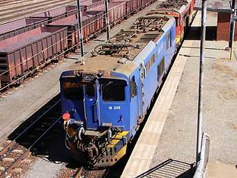
| 345 | E1684 | 6 | 1976 | 18-345 | 2007 | ex 16-427A |
| 346 | E1701 | 6 | 1976-77 | 18-346 | 2007 | ex 16-427B |
| 347 | E1718 | 6 | 1977 | 18-347 | 2007 | ex 16-428A |
| 348 | E1720 | 6 | 1977 | 18-348 | 2007 | ex 16-428B |
| 349 | E1679 | 6 | 1976 | 18-349 | 2007 | ex 16-429A |
| 350 | E1714 | 6 | 1976-77 | 18-350 | 2007 | ex 16-429B |
| 351 | E1683 | 6 | 1976 | 18-351 | 2007 | |
| 352 | E1732 | 6 | 1977 | 18-352 | 2007 | |
| 353 | E1895 | 7 | 1979 | 18-353 | 2007 | |
| 354 | E1787 | 7 | 1977 | 18-354 | 2008 | |
| 355 | E1722 | 6 | 1977 | 18-355 | 2007 | |
| 356 | E1875 | 7 | 1979 | 18-356 | 2007 | |
| 357 | E1721 | 6 | 1977 | 18-357 | 2007 | |
| 358 | E1795 | 7 | 1977-78 | 18-358 | 2007 | |
| 359 | E1846 | 7 | 1978 | 18-359 | 2007 | ex 16-404A |
| 360 | E1847 | 7 | 1978 | 18-360 | 2007 | ex 16-404B |
| 361 | E1789 | 7 | 1977-78 | 18-361 | 2007 | |
| 362 | E1886 | 7 | 1979 | 18-362 | 2007 | |
| 363 | E1863 | 7 | 1978-79 | 18-363 | 2007 | |
| 364 | E1864 | 7 | 1978-79 | 18-364 | 2007 | |
| 365 | E1833 | 7 | 1978 | 18-365 | 2007 | |
| 366 | E1748 | 7 | 1977 | 18-366 | 2007 | |
| 367 | E1743 | 6 | 1977 | 18-367 | 2007 | |
| 368 | E1853 | 7 | 1978 | 18-368 | 2007 | |
| 369 | E1817 | 7 | 1977-78 | 18-369 | 2007 | |
| 370 | E1888 | 7 | 1979 | 18-370 | 2007 | |
| 371 | E1892 | 7 | 1979 | 18-371 | 2007 | |
| 372 | E1698 | 6 | 1976-77 | 18-372 | 2008 | |
| 373 | E1665 | 6 | 1976 | 18-373 | 2008 | |
| 374 | E1879 | 7 | 1979 | 18-374 | 2007 | |
| 375 | E1692 | 6 | 1976 | 18-375 | 2008 | |
| 376 | E1973 | 8 | 1980 | 18-376 | 2007 | |
| 377 | E1764 | 7 | 1977 | 18-377 | 2008 | |
| 378 | E1970 | 8 | 1980 | 18-378 | 2008 | |
| 379 | E1799 | 7 | 1977-78 | 18-379 | 2008 | |
| 380 | E1675 | 6 | 1976 | 18-380 | 2008 | |
| 381 | E1655 | 6 | 1976 | 18-381 | 2008 | |
| 382 | E1772 | 7 | 1977 | 18-382 | 2008 | |
| 383 | E1897 | 8 | 1979 | 18-383 | 2008 | |
| 384 | E1734 | 6 | 1977 | 18-384 | 2008 | |
| 385 | E1774 | 7 | 1977 | 18-385 | 2008 | |
| 386 | E1705 | 6 | 1976-77 | 18-386 | 2008 | |
| 387 | E1830 | 7 | 1977-78 | 18-387 | 2008 | |
| 388 | E1740 | 6 | 1977 | 18-388 | 2008 | |
| 389 | E1760 | 7 | 1977 | 18-389 | 2008 | |
| 390 | E1751 | 7 | 1977 | 18-390 | 2008 | |
| 391 | E1759 | 7 | 1977 | 18-391 | 2008 | |
| 392 | E1850 | 7 | 1978 | 18-392 | 2008 | ex 16-410A |
| 393 | E1851 | 7 | 1978 | 18-393 | 2008 | ex 16-410B |
| 394 | E1712 | 6 | 1976-77 | 18-394 | 2008 | |
| 395 | E1649 | 6 | 1976 | 18-395 | 2008 | |
| 396 | E1872 | 7 | 1979 | 18-396 | 2008 | |
| 397 | E1724 | 6 | 1977 | 18-397 | 2008 | |
| 398 | E1766 | 7 | 1977 | 18-398 | 2008 | |
| 399 | E1753 | 7 | 1977 | 18-399 | 2008 | |
| 400 | E1695 | 6 | 1976 | 18-400 | 2008 | |
| 401 | E1815 | 7 | 1977-78 | 18-401 | 2008 | PRASA |
| 402 | E1819 | 7 | 1977-78 | 18-402 | 2009 | PRASA |
| 403 | E1804 | 7 | 1977-78 | 18-403 | 2008 | PRASA |
| 404 | E1711 | 6 | 1976-77 | 18-404 | 2008 | PRASA |
| 405 | E1738 | 6 | 1977 | 18-405 | 2008 | PRASA |
| 406 | E1829 | 7 | 1977-78 | 18-406 | 2008 | PRASA |
| 407 | E1758 | 7 | 1977 | 18-407 | 2009 | |
| 408 | E1756 | 7 | 1977 | 18-408 | 2009 | |
| 409 | E1821 | 7 | 1977-78 | 18-409 | 2009 | PRASA |
| 410 | E1771 | 7 | 1977 | 18-410 | 2009 | PRASA |
| 411 | E1689 | 6 | 1976 | 18-411 | 2009 | |
| 412 | E1857 | 7 | 1978 | 18-412 | 2008 | PRASA |
| 413 | E1828 | 7 | 1977-78 | 18-413 | 2008 | PRASA |
| 414 | E1868 | 7 | 1978-79 | 18-414 | 2008 | PRASA |
| 415 | E1957 | 8 | 1980 | 18-415 | 2009 | PRASA |
| 416 | E1755 | 7 | 1977 | 18-416 | 2009 | TFR, ex PRASA |
| 417 | E1786 | 7 | 1977 | 18-417 | 2009 | |
| 418 | E1779 | 7 | 1977 | 18-418 | 2009 | TFR, ex PRASA |
| 419 | E1952 | 8 | 1980 | 18-419 | 2009 | PRASA |
| 420 | E1898 | 8 | 1979 | 18-420 | 2009 | PRASA |
| 421 | E1798 | 7 | 1977-78 | 18-500 | 2009 | |
| 422 | E1802 | 7 | 1977-78 | 18-501 | 2009 | |
| 423 | E1808 | 7 | 1977-78 | 18-502 | 2009 | |
| 424 | E1709 | 6 | 1976-77 | 18-503 | 2009 | ex 16-422B |
| 425 | E1650 | 6 | 1976 | 18-504 | 2009 | |
| 426 | E1836 | 7 | 1978 | 18-505 | 2009 | |
| 427 | E1648 | 6 | 1976 | 18-506 | 2009 | |
| 428 | E1927 | 8 | 1979-80 | 18-507 | 2009 | |
| 429 | E1707 | 6 | 1976-77 | 18-508 | 2009 | |
| 430 | E1874 | 7 | 1979 | 18-509 | 2009 | |
| 431 | E1781 | 7 | 1977 | 18-510 | 2009 | |
| 432 | E1856 | 7 | 1978 | 18-511 | 2009 | |
| 433 | E1811 | 7 | 1977-78 | 18-512 | 2009 | |
| 434 | E1880 | 7 | 1979 | 18-513 | 2009 | |
| 435 | E1794 | 7 | 1977-78 | 18-514 | 2009 | |
| 436 | E1891 | 7 | 1979 | 18-515 | 2009 | |
| 437 | E1763 | 7 | 1977 | 18-516 | 2009 | |
| 438 | E1725 | 6 | 1977 | 18-517 | 2009 | |
| 439 | E1745 | 6 | 1977 | 18-518 | 2009 | |
| 440 | E1731 | 6 | 1977 | 18-519 | 2009 | |
| 441 | E1761 | 7 | 1977 | 18-520 | 2009 | |
| 442 | E1757 | 7 | 1977 | 18-521 | 2009 | |
| 443 | E1773 | 7 | 1977 | 18-522 | 2009 | |
| 444 | E1865 | 7 | 1978-79 | 18-523 | 2009 | |
| 445 | E1825 | 7 | 1977-78 | 18-524 | 2009 | |
| 446 | E1706 | 6 | 1976-77 | 18-525 | 2009 | |
Models and liveries
The Class 6E1 series lineage identification features as well as the liveries that were applied to these loomotives are illustrated in the following pictures. Note the external compressed air pipe on the right side of locomotives rebuilt from Class 6E1, Series 6 and 7.
- Rebuilt from Class 6E1, Series 6
-
No. 18-349 (E1679) in Spoornet blue livery with outline numbers at Warrenton, 2 May 2013
-
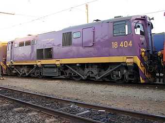
No. 18-404 (E1711) in PRASA's purple Shosholoza Meyl livery at Sentrarand, 8 October 2009
-
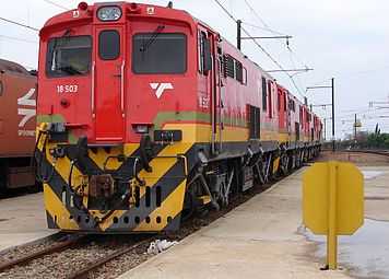
No. 18-503 (E1709) in Transnet Freight Rail livery at Sentrarand, Gauteng, 29 September 2009
- Rebuilt from Class 6E1, Series 7
-
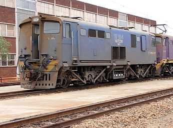
No. 18-184 (E1790) in Spoornet blue with outline numbers, Sentrarand, 29 September 2009
-
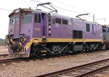
No. 18-418 (E1779) in PRASA's purple Shosholoza Meyl livery at Sentrarand, 29 September 2009
-
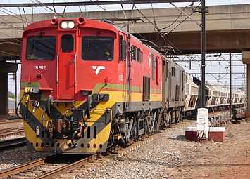
No. 18-512 (E1811) in Transnet Freight Rail livery at Kaalfontein, Gauteng, 28 September 2009
- Rebuilt from Class 6E1, Series 8
-
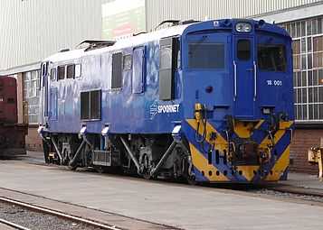
No. 18-001 (E1954) in Spoornet blue livery with outline numbers at Koedoespoort, 2 October 2009
-
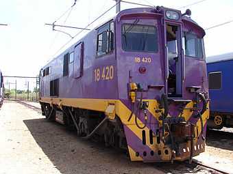
No. 18-420 (E1898) in PRASA's purple Shosholoza Meyl livery at Pyramid South, 6 October 2009
-
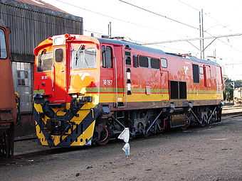
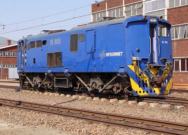
No. 18-197 (E1944) in Transnet Freight Rail livery at Capital Park, Pretoria, 9 October 2009
- Rebuilt from Class 6E1, Series 9
-
No. 18-009 (E2004) with a toilet side window, at Capital Park, Pretoria, 29 September 2006
-
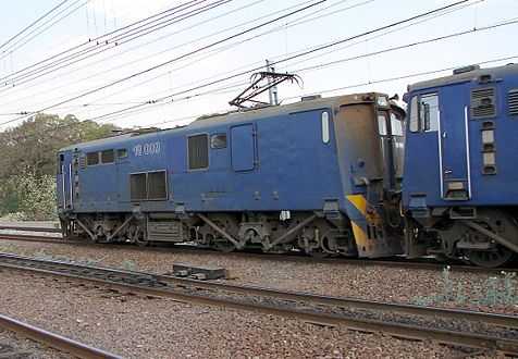
No. 18-328 (E2071) with no toilet window, at Sentrarand, Gauteng, 22 September 2009
- Rebuilt from Class 6E1, Series 10
-
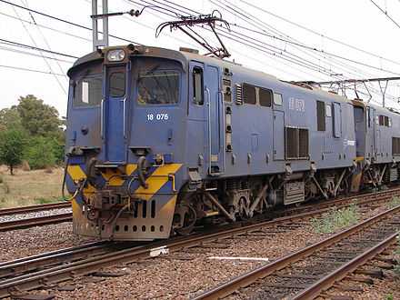
No. 18-076 (E2124) with covered drainage holes at Capital Park, Pretoria, 2 October 2006
-
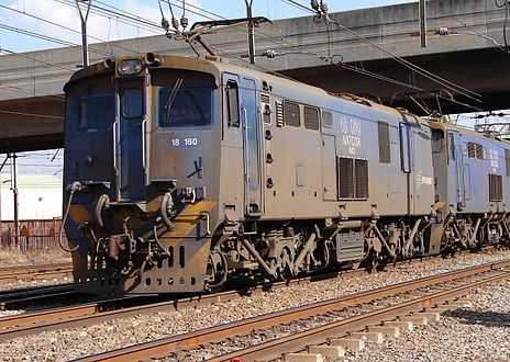
No. 18-160 (E2104) with uncovered drainage holes at Kaalfontein, 23 September 2009
- Rebuilt from Class 6E1, Series 11
-
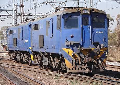
No. 18-048 (E2180) with covered drainage holes at Capital Park, Pretoria, 20 August 2007
-
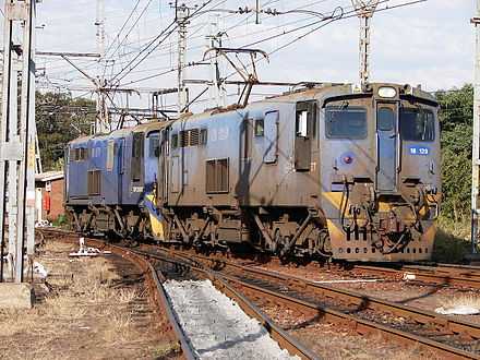
No. 18-129 (E2172) with uncovered drainage holes at Capital Park, 10 May 2013
See also
- Electric locomotive numbering and classification
- List of South African locomotive classes
- South African Class 6E1, Series 6
- South African Class 6E1, Series 7
- South African Class 6E1, Series 8
- South African Class 6E1, Series 9
- South African Class 6E1, Series 10
- South African Class 6E1, Series 11
- South African Class 16E
- South African Class 17E
- South African Class 18E, Series 2
- South African locomotive history
References
|
- ↑ 1.0 1.1 1.2 1.3 1.4 1.5 1.6 1.7 1.8 1.9 1.10 Information gathered from the rebuild files of individual locomotives at Transnet Rail Engineering’s Koedoespoort shops, or obtained from John Middleton as well as several Transnet employees
- ↑ 2.0 2.1 2.2 2.3 South African Railways Index and Diagrams Electric and Diesel Locomotives, 610mm and 1065mm Gauges, Ref LXD 14/1/100/20, 28 January 1975, as amended
- ↑ 3.0 3.1 3.2 3.3 3.4 3.5 Middleton, John N. (2002). Railways of Southern Africa Locomotive Guide - 2002 (as amended by Combined Amendment List 4, January 2009) (2nd, Dec 2002 ed.). Herts, England: Beyer-Garratt Publications. pp. 49, 51, 57–58.
- ↑ "UCW - Electric locomotives" (PDF). The UCW Partnership. Archived from the original (PDF) on 12 October 2007. Retrieved 30 September 2010.
- ↑ 5.0 5.1 5.2 Information obtained from Transnet engineers and drivers
- ↑ 6.0 6.1 6.2 6.3 18E Locomotive (TFR leaflet used in driver training, circa 2010)
- ↑ 7.0 7.1 7.2 7.3 7.4 Operation - South African Classes 6E, 6E1, 16E, 17E and 18E