Slope deflection method
The slope deflection method is a structural analysis method for beams and frames introduced in 1914 by George A. Maney.[1] The slope deflection method was widely used for more than a decade until the moment distribution method was developed.
Introduction
By forming slope deflection equations and applying joint and shear equilibrium conditions, the rotation angles (or the slope angles) are calculated. Substituting them back into the slope deflection equations, member end moments are readily determined.
Slope deflection equations
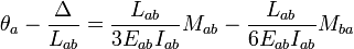
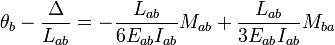
The slope deflection equations can also be written using the stiffness factor  and the chord rotation
  :
:
Derivation of slope deflection equations
When a simple beam of length  and flexural rigidity
  is loaded at each end with clockwise moments
  and
and  , member end rotations occur in the same direction. These rotation angles can be calculated using the unit dummy force method or Darcy's Law.
Rearranging these equations, the slope deflection equations are derived.
Equilibrium conditions
Joint equilibrium
Joint equilibrium conditions imply that each joint with a degree of freedom should have no unbalanced moments i.e. be in equilibrium. Therefore,
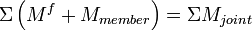
Here,  are the member end moments,
  are the fixed end moments, and
  are the external moments directly applied at the joint.
Shear equilibrium
When there are chord rotations in a frame, additional equilibrium conditions, namely the shear equilibrium conditions need to be taken into account.
Example
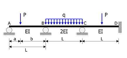
The statically indeterminate beam shown in the figure is to be analysed.
- Members AB, BC, CD have the same length
 .
. - Flexural rigidities are EI, 2EI, EI respectively.
- Concentrated load of magnitude
 acts at a distance
  from the support A.
 - Uniform load of intensity
 acts on BC.
 - Member CD is loaded at its midspan with a concentrated load of magnitude .
In the following calculations, clockwise moments and rotations are positive.
Degrees of freedom
Rotation angles  ,
,  ,
,  , of joints A, B, C, respectively are taken as the unknowns. There are no chord rotations due to other causes including support settlement.
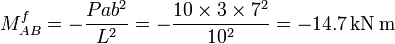
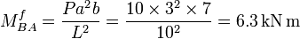
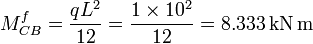
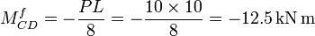
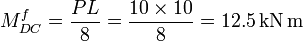
Fixed end moments
Fixed end moments are:
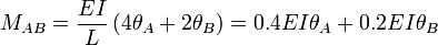
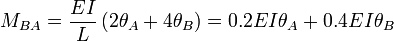
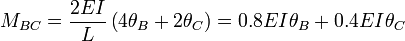
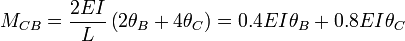
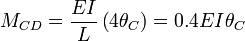
Slope deflection equations
The slope deflection equations are constructed as follows:
Joint equilibrium equations
Joints A, B, C should suffice the equilibrium condition. Therefore


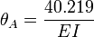
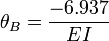
Rotation angles
The rotation angles are calculated from simultaneous equations above.

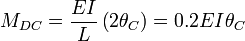
Member end moments
Substitution of these values back into the slope deflection equations yields the member end moments (in kNm):


See also
- Beam theory
Notes
- ↑ Maney, George A. (1915). "Studies in Engineering". Minneapolis: University of Minnesota.
References
- Norris, Charles Head; John Benson Wilbur; Senol Utku (1976). Elementary Structural Analysis (3rd ed.). McGraw-Hill. pp. 313–326. ISBN 0-07-047256-4.
- McCormac, Jack C.; James K. Nelson, Jr. (1997). Structural Analysis: A Classical and Matrix Approach (2nd ed.). Addison-Wesley. pp. 430–451. ISBN 0-673-99753-7.
- Yang, Chang-hyeon (2001-01-10). Structural Analysis (in Korean) (4th ed.). Seoul: Cheong Moon Gak Publishers. pp. 357–389. ISBN 89-7088-709-1.