Siphon
- For the carbonation device, see soda siphon.


The word siphon (from Ancient Greek: σίφων "pipe, tube", also called syphon) is used to refer to a wide variety of devices that involve the flow of liquids through tubes, see siphon terminology. By definition the word refers specifically to a tube in an inverted 'U' shape which causes a liquid to flow upward above the surface of a reservoir, with no pump but powered by the fall of the liquid as it flows down the tube under the pull of gravity, and discharging at a level lower than the surface of the reservoir whence it came. Note that while the siphon intake tube must be below the surface of the liquid in the higher reservoir, it need not touch the liquid in the lower reservoir and indeed there need not be a lower reservoir; a siphon can discharge into mid-air so long as the exit is below the surface of the upper reservoir.
In practical siphons, atmospheric pressure pushes the liquid up the tube into the region of reduced pressure at the top of the tube in the same way as a manometer, and indeed the maximum height of a vacuum started siphon is the same as the height of a manometer exposed to the atmosphere, because they operate by the same mechanism. The reduced pressure is caused by liquid falling on the exit side.[1][2][3][4]
While in everyday siphons, atmospheric pressure is the driving mechanism, in specialized circumstances other mechanisms can work – in the laboratory, some siphons have been demonstrated to work in a vacuum[5][4][6][7][8] – see vacuum siphons – indicating the tensile strength of the liquid is contributing to the operation of siphons at very low pressures.
Siphons are generally governed by Bernoulli's principle.[9] This is simply a restatement of conservation of energy principle in that the sum of all energy at any given point in the siphon flow is constant. Because the reservoir generally has a constant energy per unit volume (the sum of pressure energy and gravitational potential energy is constant), the outlet must also have the same energy. The outlet has lower gravitational potential energy due to the height difference and increased kinetic energy (or dynamic pressure).
Siphons share many characteristics with other fluid systems such as manometers. Specifically, all the principles regarding hydraulic head, including the limitations on lift of the working fluid, are valid (i.e. the fluid pressure can't be negative at any point in the system so there is a maximum energy tradeoff between fluid pressure and gravitational potential energy). Unlike a manometer, which operates as a measurement of two pressures in static balance (often the atmospheric pressure and vapor pressure of the liquid), a siphon is in balance when the inlet and the outlet are at the same level. The gravitational energy, pressure energy and flow energy are the same at inlet and outlet when they are in static balance in a siphon whereas in a manometer, gravitational potential energy and pressure energy are exchanged until static equilibrium is achieved. When the outlet of a siphon is lowered from the static case, gravitational potential energy decreases and is converted into a fluid pressure difference and velocity of the fluid to satisfy conservation of energy. The flow and energy change at the outlet propagates back through the fluid at the acceleration of gravity in the fluid as the energy at any point must still be equal. The conditions at the inlet are unchanged, so all the energy changes in the siphon fluid are in pressure of the fluid and its velocity.
Consequently, a siphon can be described as the sum of various types of head that represent the total energy in the system. The equation is written between any two points a and b in a system that contain the same fluid.

where:
- p = pressure of the fluid
- γ = ρg = density·acceleration of gravity = specific weight of the fluid.[11]
- v = velocity of the fluid
- g = acceleration of gravity
- z = elevation
 = pressure head
 = velocity head
History
Egyptian reliefs from 1500 BC depict siphons used to extract liquids from large storage jars.[12][13]
There is physical evidence for the use of siphons by Greek engineers in the 3rd century BC at Pergamon.[14][15]
Hero of Alexandria wrote extensively about siphons in the treatise Pneumatica.[16]
In the 9th century, the Banu Musa brothers invented a double-concentric siphon, which they described in their Book of Ingenious Devices.[17][18] The edition edited by Hill includes an analysis of the double-concentric siphon.
Siphons were studied further in the 17th century, in the context of suction pumps (and the recently developed vacuum pumps), particularly with an eye to understanding the maximum height of pumps (and siphons) and the apparent vacuum at the top of early barometers. This was initially explained by Galileo Galilei via the theory of horror vacui ("nature abhors a vacuum"), which dates to Aristotle, and which Galileo restated as resintenza del vacuo, but this was subsequently disproved by later workers, notably Evangelista Torricelli and Blaise Pascal[19] – see barometer: history.

Specifically, Pascal demonstrated that siphons work via gravity and they can be initialized by converting gravitational potential energy into pressure. Two beakers of mercury are placed in a large container, at different heights. The beakers are connected with a three-way tube: a regular siphon (U-shaped tube), with an additional tube extending upward from the hook in the tube: one end of the tube goes down into each beaker (as in a normal siphon), while the third end faces upward, and is open to the air. The large container is slowly filled with water (the tube remains open to the air): as water level rises in the container, the height of the water increases which raises the energy of the liquid and the head associated with it. The mercury rises in both sides of the tube (upper and lower) and each tube is level with each other once the lower tube reaches the upper reservoir surface. A siphon will start when the height of the water adds enough water gravitational head to increase the mercury head (the head required is determined by the relative densities). Note, that in terms of pressure head, the lower vessel of mercury has more water pressure than the upper vessel. In the water vessel, the sum of gravitational and pressure energy per unit volume for a given level of water is constant throughout the vessel (the head is simply the height of the water). As energy is added by filling the vessel with water (i.e. head increases as the water level increases, the lower mercury vessel will be submerged first and liquid will begin rising in the "down" tube until it reaches the surface of the upper mercury vessel. At that point, raising the water level continues to add more gravitational head and the mercury will rise in both tubes equally as long water height is increased. When the mercury reaches the cross beam, syphon flow starts. Note that even though there is more pressure on the lower reservoir, the flow direction is determined by the height difference as the mercury seeks a level that is equal between both containers. Thus mercury flows against absolute pressure differences as pressure is not a factor in the flow of a siphon but gravity is.
Theory
A siphon works because gravitational potential energy difference between liquid in the upper reservoir and lower reservoir leaves reduced pressure at the top of the siphon proportional to the height differences. The pressure reduces as the height of the liquid is increased. As long as the pressure maintains the fluid as a liquid throughout the system, a siphon will continue.[20][21] The main issue in siphons is due primarily to the pressure at the top of the siphon maintaining a liquid phase. The pressure difference is caused by gravitational energy difference that is exchanged for flow velocity of the fluid and pressure in the fluid. The sum of pressure energy , kinectic energy and gravitational potential energy is constant through the fluid.
In more detail, one can look at how the hydrostatic pressure varies through the siphon, considering in turn the vertical tube from the top reservoir, the vertical tube from the bottom reservoir, and the horizontal tube connecting them (assuming a U-shape). At liquid level in the top reservoir, the liquid is under atmospheric pressure, and as one goes up the siphon, the hydrostatic pressure decreases and the hydrostatic pressure at the top of the tube is then lower than atmospheric pressure by an amount proportional to the height of the tube plus the kinetic energy of the fluid. The sum of energy is constant as it is transformed between kinetic, pressure and gravitational energy. The siphon requires that the lower reservoir is lower than the upper reservoir, or more generally that the discharge outlet simply be lower than the surface of the upper reservoir as the net energy difference is gravitational. Tube diameter, fluid weight in different sections and tube shape are largely irrelevant as fluid energy is constant throughout the connected fluid.


In non-ideal fluids, compressibility, tensile strength and other characteristics of the working fluid (or multiple fluids) complicate Bernoulli's equation but the underlying principle that gravity is the only force that maintains the siphon. An occasional misunderstanding of siphons is that they rely on the tensile strength of the liquid to pull the liquid up and over the rise.[20][21] While water has been found to have a great deal of tensile strength in some experiments (such as with the z-tube[22]), and siphons in vacuum rely on such cohesion, common siphons can easily be demonstrated to need no liquid tensile strength at all to function.[20][21][7] Furthermore, since common siphons operate at positive pressures throughout the siphon, there is no contribution from liquid tensile strength, because the liquid is incompressible, rather than pulling on each other.[7] To demonstrate, the longer lower leg of a common siphon can be plugged at the bottom and filled almost to the crest with liquid as in Figure 4, leaving the top and the shorter upper leg completely dry and containing only air. When the plug is removed and the liquid in the longer lower leg is allowed to fall, the liquid in the upper reservoir will then typically sweep the air bubble down and out of the tube. The apparatus will then continue to operate as a siphon. As there is no contact between the liquid on either side of the siphon at the beginning of this experiment, there can be no cohesion between the liquid molecules to pull the liquid over the rise.
The uphill flow of water in a siphon doesn't violate the principle of continuity because it is not connected to the downward flow and the volume of the bubble is not static. The mass of water entering the tube and flowing upwards is less than the mass of water flowing downwards and leaving the tube which causes the bubble to expand in volume and reduce in pressure. The differential pressure acts like the suction and vacuum pumps and as long as the downward tube can create the pressure difference necessary to start the siphon, it will continues. A siphon doesn't violate the principle of conservation of energy because the loss of gravitational potential energy as liquid flows from the upper reservoir to the lower reservoir equals the work done.[23] Once started, a siphon requires no additional energy to keep the liquid flowing up and out of the reservoir. The siphon will draw liquid out of the reservoir until the level falls below the intake, allowing air or other surrounding gas to break the siphon, or until the outlet of the siphon equals the level of the reservoir, whichever comes first.
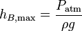
In addition to atmospheric pressure, the density of the liquid, and gravity, the maximum height of the crest is limited by the vapour pressure of the liquid. When the pressure within the liquid drops to below the liquid's vapor pressure, tiny vapor bubbles can begin to form at the high point and the siphon effect will end. This effect depends on how efficiently the liquid can nucleate bubbles; in the absence of impurities or rough surfaces to act as easy nucleation sites for bubbles, siphons can temporarily exceed their standard maximum height during the extended time it takes bubbles to nucleate. For water at standard atmospheric pressure, the maximum siphon height is approximately 10 m (32 feet); for mercury it is 76 cm (30 inches), which is the definition of standard pressure. This equals the maximum height of a suction pump, which operates by the same principle.[24] The ratio of heights (about 13.6) equals the ratio of densities of water and mercury (at a given temperature), since the column of water (resp. mercury) is balancing with the column of air yielding atmospheric pressure, and indeed maximum height is (neglecting vapor pressure and velocity of liquid) inversely proportional to density of liquid.
Modern research into the operation of the siphon
In 1948, Malcolm Nokes investigated siphons working in both air pressure and in a partial vacuum, for siphons in vacuum he concluded that: "The gravitational force on the column of liquid in the downtake tube less the gravitational force in the uptake tube causes the liquid to move. The liquid is therefore in tension and sustains a longitudinal strain which, in the absence of disturbing factors, is insufficient to break the column of liquid". But for siphons of small uptake height working at atmospheric pressure, he concluded that: "... the tension of the liquid column is neutralized and reversed by the compressive effect of the atmosphere on the opposite ends of the liquid column."[7]
Potter and Barnes at the University of Edinburgh revisited siphons in 1971. They re-examined the theories of the siphon and ran experiments on siphons in air pressure. Their conclusion was that it "...is the cohesion of the liquid rather than the pressure of an external atmosphere which is crucial to the working of a siphon." [25]
Gravity, pressure and molecular cohesion were the focus of work in 2010 by Hughes at the Queensland University of Technology. He used siphons at air pressure and his conclusion was that: "The flow of water out of the bottom of a siphon depends on the difference in height between the inflow and outflow, and therefore cannot be dependent on atmospheric pressure…"[26] Hughes did further work on siphons at air pressure in 2011 and concluded that: "The experiments described above demonstrate that ordinary siphons at atmospheric pressure operate through gravity and not atmospheric pressure".[27]
The father and son researchers, Ramette and Ramette, successfully siphoned carbon dioxide under air pressure in 2011 and concluded that molecular cohesion is not required for the operation of a siphon but that: "The basic explanation of siphon action is that, once the tube is filled, the flow is initiated by the greater pull of gravity on the fluid on the longer side compared with that on the short side. This creates a pressure drop throughout the siphon tube, in the same sense that 'sucking' on a straw reduces the pressure along its length all the way to the intake point. The ambient atmospheric pressure at the intake point responds to the reduced pressure by forcing the fluid upwards, sustaining the flow, just as in a steadily sucked straw in a milkshake."[1]
Again in 2011, Richert and Binder (at the University of Hawaii) examined the siphon and concluded that molecular cohesion is not required for the operation of a siphon but relies upon gravity and a pressure differential, writing: "As the fluid initially primed on the long leg of the siphon rushes down due to gravity, it leaves behind a partial vacuum that allows pressure on the entrance point of the higher container to push fluid up the leg on that side".[2]
A research team at the University of Nottingham succeeded in running a siphon in high vacuum, also in 2011. They wrote that: "It is widely believed that the siphon is principally driven by the force of atmospheric pressure. An experiment is described that shows that a siphon can function even under high-vacuum conditions. Molecular cohesion and gravity are shown to be contributing factors in the operation of a siphon; the presence of a positive atmospheric pressure is not required".[28]
Writing in Physics Today in 2011, J. Dooley from Millersville University stated that both a pressure differential within the siphon tube and the tensile strength of the liquid are required for a siphon to operate.[29]
A researcher at Humboldt State University, A. McGuire, examined flow in siphons in 2012. Using the advanced general-purpose multiphysics simulation software package LS-DYNA he examined pressure initialisation, flow, and pressure propagation within a siphon. He concluded that: "Pressure, gravity and molecular cohesion can all be driving forces in the operation of siphons".[3]
In 2014, Hughes and Gurung (at the Queensland University of Technology), ran a water siphon under varying air pressures ranging from sea level to 11.9 km (39000 ft) altitude. They noted that: "Flow remained more or less constant during ascension indicating that siphon flow is independent of ambient barometric pressure". They used Bernoulli's equation and the Poiseuille equation to examine pressure differentials and fluid flow within a siphon. Their conclusion was that: "It follows from the above analysis that there must be a direct cohesive connection between water molecules flowing in and out of a siphon. This is true at all atmospheric pressures in which the pressure in the apex of the siphon is above the vapour pressure of water, an exception being ionic liquids".[30]
Siphon coffee

While if both ends of a siphon are at atmospheric pressure, liquid flows from high to low, if the bottom end of a siphon is pressurized, liquid can flow from low to high. If pressure is removed from the bottom end, the liquid flow will reverse, illustrating that it is pressure driving the siphon. An everyday illustration of this is the siphon coffee brewer, which works as follows (designs vary; this is a standard design, omitting coffee grounds):
- a glass vessel is filled with water, then corked (so air-tight) with a siphon sticking vertically upwards
- another glass vessel is placed on top, open to the atmosphere – the top vessel is empty, the bottom is filled with water
- the bottom vessel is then heated; as the temperature increases, the vapor pressure of the water increases (it increasingly evaporates); when the water boils the vapor pressure equals atmospheric pressure, and as the temperature increases above boiling the pressure in the bottom vessel then exceeds atmospheric pressure, and pushes the water up the siphon tube into the upper vessel.
- a small amount of still hot water and steam remain in the bottom vessel and are kept heated, with this pressure keeping the water in the upper vessel
- when the heat is removed from the bottom vessel, the vapor pressure decreases, and can no longer support the column of water – gravity (acting on the water) and atmospheric pressure then push the water back into the bottom vessel.
In practice, the top vessel is filled with coffee grounds, and the heat is removed from the bottom vessel when the coffee has finished brewing. What vapor pressure means concretely is that the boiling water converts high-density water (a liquid) into low-density steam (a gas), which thus expands to take up more volume (in other words, the pressure increases). This pressure from the expanding steam then forces the liquid up the siphon; when the steam then condenses down to water the pressure decreases and the liquid flows back down.
Chain analogy
A simplified but misleading conceptual model of a siphon is that it is like a chain hanging over a pulley with one end of the chain piled on a higher surface than the other. Since the length of chain on the shorter side is lighter than the length of chain on the taller side, the chain will move up around the pulley and down towards the lower surface.[31]
There are a number of problems with the chain model of a siphon, and understanding these differences helps to explain the actual workings of siphons. That is, under most practical circumstances, dissolved gases, vapor pressure, and (sometimes) lack of adhesion with tube walls, conspire to render the tensile strength within the liquid ineffective for siphoning. Thus, unlike a chain which has significant tensile strength, liquids usually have little tensile strength under typical siphon conditions, and therefore the liquid on the rising side cannot be pulled up, in the way the chain is pulled up on the rising side.[21][7]
A related problem is that siphons have a maximum height (for water siphons at standard atmospheric pressure, about 10 meters), as this is the limit determined by the difference in source side pressure and the vapor pressure of the liquid equaling the weight of liquid in column, but the chain model has no such limit – or rather is instead limited by how strong the links are (above a certain height, the chain links could not support the weight of the hanging chain and the links would snap), corresponding to tensile strength of the liquid, which is not the cause of maximum height in siphons.

A further problem with the chain model of the siphon is that siphons work by a hydrodynamic gradient of pressure energy within the siphon being traded for gravitational energy and fluid velocity, not by absolute differences of weight on either side. The weight of liquid on the up side of the siphon can be greater than the liquid on the down side, yet the siphon can still function as the mass flow rate is the same but the velocity in the different sections is different causing a pressure difference described by Bernoulli's principle. For example, if the tube from the upper reservoir to the top of the siphon has a much larger diameter than the section of tube from the lower reservoir to the top of the siphon, the shorter upper section of the siphon may have a much larger weight of liquid in it, a slower velocity, yet the siphon can function normally[32]
Despite these shortcomings, in some situations siphons do function in the absence of atmospheric pressure and via tensile strength – see vacuum siphons – and in these situations the chain model can be instructive. Further, in other settings water transport does occur via tension, most significantly in transpirational pull in the xylem of vascular plants.[20]
Practical requirements
A plain tube can be used as a siphon. An external pump has to be applied to start the liquid flowing and prime the siphon. This can be a human mouth. This is sometimes done with any leak-free hose to siphon gasoline from a motor vehicle's gasoline tank to an external tank. (Siphoning gasoline by mouth often results in the accidental swallowing of gasoline, or aspirating it into the lungs, which can cause death or lung damage.[33]) If the tube is flooded with liquid before part of the tube is raised over the intermediate high point and care is taken to keep the tube flooded while it is being raised, no pump is required. Devices sold as siphons often come with a siphon pump to start the siphon process.
In some applications it can be helpful to use siphon tubing that is not much larger than necessary. Using piping of too great a diameter and then throttling the flow using valves or constrictive piping appears to increase the effect of previously cited concerns over gases or vapor collecting in the crest which serve to break the vacuum. If the vacuum is reduced too much, the siphon effect can be lost. Reducing the size of pipe used closer to requirements appears to reduce this effect and creates a more functional siphon that does not require constant re-priming and restarting. In this respect, where the requirement is to match a flow into a container with a flow out of said container (to maintain a constant level in a pond fed by a stream, for example) it would be preferable to utilize two or three smaller separate parallel pipes that can be started as required rather than attempting to use a single large pipe and attempting to throttle it.
Siphon pump
While a simple siphon cannot output liquid at a level higher than the source reservoir, a more complicated device utilizing an airtight chamber at the crest and a system of automatic valves, may discharge liquid on an ongoing basis, at a level higher than the source reservoir, without outside pumping energy being added. It can accomplish this despite what initially appears to be a violation of conservation of energy because it can take advantage of the energy of a large volume of liquid dropping some distance, to raise and discharge a small volume of liquid above the source reservoir. Thus it might be said to "require" a large quantity of falling liquid to power the dispensing of a small quantity. Such a system typically operates in a cyclical or start/stop but ongoing and self-powered manner.[34][35] Ram pumps do not work in this way.
Applications

When certain liquids needs to be purified, siphoning can help prevent either the bottom (dregs) or the top (foam and floaties) from being transferred out of one container into a new container. Siphoning is thus useful in the fermentation of wine and beer for this reason, since it can keep unwanted impurities out of the new container.
Self-constructed siphons, made of pipes or tubes, can be used to evacuate water from cellars after floodings. Between the flooded cellar and a deeper place outside a connection is built, using a tube or some pipes. They are filled with water through an intake valve (at the highest end of the construction). When the ends are opened, the water flows through the pipe into the sewer or the river.
Siphoning is common in irrigated fields to transfer a controlled amount of water from a ditch, over the ditch wall, into furrows.

Large siphons may be used in municipal waterworks and industry. Their size requires control via valves at the intake, outlet and crest of the siphon. The siphon may be primed by closing the intake and outlets and filling the siphon at the crest. If intakes and outlets are submerged, a vacuum pump may be applied at the crest to prime the siphon. Alternatively the siphon may be primed by a pump at either the intake or outlet.
Gas in the liquid is a concern in large siphons.[36] The gas tends to accumulate at the crest and if enough accumulates to break the flow of liquid, the siphon stops working. The siphon itself will exacerbate the problem because as the liquid is raised through the siphon, the pressure drops, causing dissolved gases within the liquid to come out of solution. Higher temperature accelerates the release of gas from liquids so maintaining a constant, low temperature helps. The longer the liquid is in the siphon, the more gas is released, so a shorter siphon overall helps. Local high points will trap gas so the intake and outlet legs should have continuous slopes without intermediate high points. The flow of the liquid moves bubbles thus the intake leg can have a shallow slope as the flow will push the gas bubbles to the crest. Conversely, the outlet leg needs to have a steep slope to allow the bubbles to move against the liquid flow; though other designs call for a shallow slope in the outlet leg as well to allow the bubbles to be carried out of the siphon. At the crest the gas can be trapped in a chamber above the crest. The chamber needs to be occasionally primed again with liquid to remove the gas.
Siphon terminology
Bowl siphon
Bowl siphons are part of flush toilets. Although called a 'siphon' they are not actually a siphon. The name refers to the inverted 'U' of the plumbing attached to the toilet bowl. Water poured into the bowl during the flush increases the total volume of the water from its resting volume and so the water level rises above the lower part of the plumbing and the excess simply drains away until the resting volume returns.[37]
Some toilets also use the siphon principle to obtain the actual flush from the cistern. The flush is triggered by a lever or handle that operates a simple diaphragm-like piston pump that lifts enough water to the crest of the siphon to start the flow of water which then completely empties the contents of the cistern into the toilet bowl. The advantage of this system was that no water would leak from the cistern excepting when flushed. These were mandatory in the UK until 2011.[38]
Early urinals incorporated a siphon in the cistern which would flush automatically on a regular cycle because there was a constant trickle of clean water being fed to the cistern by a slightly open valve.
Inverted siphon

An inverted siphon is not a siphon but a term applied to pipes that must dip below an obstruction to form a "U" shaped flow path.
Large inverted siphons are used to convey water being carried in canals or flumes across valleys, for irrigation or gold mining. The Romans used inverted siphons of multiple lead pipes to cross valleys that were too big to construct an aqueduct.[39][40][41]
Inverted siphons are commonly called traps for their function in preventing smelly sewer gases from coming back out of drains[42] and sometimes making dense objects like rings and electronic components retrievable after falling into a drain.[43][44] Liquid flowing in one end simply forces liquid up and out the other end, but solids like sand will accumulate. This is especially important in sewage systems or culverts which must be routed under rivers or other deep obstructions where the better term is "depressed sewer".[45][46]
Back siphonage
Back siphonage is a plumbing term applied to the reversal of normal water flow in a plumbing system due to sharply reduced or negative pressure on the water supply side, such as high demand on water supply by fire-fighting;[47] it is not an actual siphon as it is suction.[48] Back siphonage is rare as it depends on submerged inlets at the outlet (home) end and these are uncommon.[49] Back siphonage is not to be confused with backflow; which is the reversed flow of water from the outlet end to the supply end caused by pressure occurring at the outlet end.[49]
Anti-siphon valve
Building codes often contain specific sections on back siphonage and especially for external faucets (See the sample building code quote, below). Backflow prevention devices such as anti-siphon valves[50] are required in such designs. The reason is that external faucets may be attached to hoses which may be immersed in an external body of water, such as a garden pond, swimming pool, aquarium or washing machine. In these situations the flow is not actually a siphon but suction due to reduced pressure on the water supply side. Should the pressure within the water supply system fall, the external water may be returned by back pressure into the drinking water system through the faucet. Another possible contamination point is the water intake in the toilet tank. An anti-siphon valve is also required here to prevent pressure drops in the water supply line from suctioning water out of the toilet tank (which may contain additives such as "toilet blue"[51]) and contaminating the water system. Anti-siphon valves function as a one-direction check valve.
Anti-siphon valves are also used medically. Hydrocephalus, or excess fluid in the brain, may be treated with a shunt which drains cerebrospinal fluid from the brain. All shunts have a valve to relieve excess pressure in the brain. The shunt may lead into the abdominal cavity such that the shunt outlet is significantly lower than the shunt intake when the patient is standing. Thus a siphon effect may take place and instead of simply relieving excess pressure, the shunt may act as a siphon, completely draining cerebrospinal fluid from the brain. The valve in the shunt may be designed to prevent this siphon action so that negative pressure on the drain of the shunt does not result in excess drainage. Only excess positive pressure from within the brain should result in drainage.[52][53][54]
Note that the anti-siphon valve in medical shunts is preventing excess forward flow of liquid. In plumbing systems, the anti-siphon valve is preventing backflow.
Sample building code regulations regarding "back siphonage" from the Canadian province of Ontario:[55]
- 7.6.2.3.Back Siphonage
- Every potable water system that supplies a fixture or tank that is not subject to pressures above atmospheric shall be protected against back-siphonage by a backflow preventer.
- Where a potable water supply is connected to a boiler, tank, cooling jacket, lawn sprinkler system or other device where a non-potable fluid may be under pressure that is above atmospheric or the water outlet may be submerged in the non-potable fluid, the water supply shall be protected against backflow by a backflow preventer.
- Where a hose bibb is installed outside a building, inside a garage, or where there is an identifiable risk of contamination, the potable water system shall be protected against backflow by a backflow preventer.
Other anti-siphoning devices
Along with anti-siphon valves, anti-siphoning devices also exist. The two are unrelated in application. Siphoning can be used to remove fuel from tanks. With the cost of fuel increasing, it has been linked in several countries to the rise in fuel theft. Trucks, with their large fuel tanks, are most vulnerable. The anti-siphon device prevents thieves from inserting a tube into the fuel tank.
Siphon barometer
A siphon barometer is the term sometimes applied to the simplest of mercury barometers. A continuous U-shaped tube of the same diameter throughout is sealed on one end and filled with mercury. When placed into the upright, "U", position, mercury will flow away from the sealed end, forming a partial vacuum, until balanced by atmospheric pressure on the other end. The term "siphon" derives from the mistaken belief that air pressure is involved in the operation of a siphon. The difference in height of the fluid between the two arms of the U-shaped tube is the same as the maximum intermediate height of a siphon. When used to measure pressures other than atmospheric pressure, a siphon barometer is sometimes called a siphon gauge, these are not siphons but follow a standard 'U'-shaped design[56] leading to the term. Siphon barometers are still produced as precision instruments.[57] Siphon barometers should not be confused with a siphon rain gauge.[58]
Siphon bottle

A siphon bottle (also called a soda syphon or, archaically, a siphoid[59]) is a pressurized bottle with a vent and a valve. It is not a siphon as pressure within the bottle drives the liquid up and out a tube. A special form was the gasogene.
Siphon cup
A siphon cup is the (hanging) reservoir of paint attached to a spray gun, it is not a siphon as a vacuum pump extracts the paint.[60] This is to distinguish it from gravity-fed reservoirs. An archaic use of the term is a cup of oil in which the oil is transported out of the cup via a cotton wick or tube to a surface to be lubricated, this is not a siphon but an example of capillary action.
Siphon rain gauge
A siphon rain gauge is a rain gauge that can record rainfall over an extended period. A siphon is used to automatically empty the gauge. It is often simply called a "siphon gauge" and is not to be confused with a siphon pressure gauge.
Heron's siphon
Heron's siphon is not a siphon as it works as a gravity driven pressure pump,[61][62] at first glance it appears to be a perpetual motion machine but will stop when the air in the priming pump is depleted. In a slightly differently configuration, it is also known as Heron's fountain.[63]
Venturi siphon
A venturi siphon, also known as an eductor, is not a siphon but a form of vacuum pump using the Venturi effect of fast flowing fluids (e.g. air), to produce low pressures to suction other fluids; a common example is the carburetor. See pressure head. The low pressure at the throat of the venturi is called a siphon when a second fluid is introduced, or an aspirator when the fluid is air, this is an example of the misconception that air pressure is the operating force for siphons.
Siphonic roof drainage
Despite the name, siphonic roof drainage does not work as a siphon; the technology makes use of gravity induced vacuum pumping[64] to carry water horizontally from multiple roof drains to a single downpipe and to increase flow velocity.[65] Metal baffles at the roof drain inlets reduce the injection of air which increases the efficieny of the system.[66] One benefit to this drainage technique is reduced capital costs in construction compared to traditional roof drainage.[64] Another benefit is the elimination of pipe pitch or gradient required for conventional roof drainage piping. However this system of gravity pumping is mainly suitable for large buildings and is not usually suitable for residential properties.[66]
Siphon spillway
A siphon spillway in a dam is usually not technically a siphon as they are generally used to drain elevated water levels.[67] A siphon spillway operates as a siphon if flow is raised higher than the water surface, as sometimes used in irrigation,[68][69] in operation a siphon spillway is considered to be 'pipe flow' or 'closed duct flow'.[70][71] A normal spillway flow is pressurized by the height of the reservoir above the spillway whereas a siphon flow rate is governed by the difference in height of the inlet and outlet.[72] Some designs make use an automatic system that uses the flow of water in a spiral vortex to remove the air above to prime the siphon. Such a design includes the volute siphon.[73]
Self-siphons
The term self-siphon is used in a number of ways. Liquids that are composed of long polymers can "self-siphon"[74][75] and these liquids do not depend on atmospheric pressure. Self-siphoning polymer liquids work the same as the siphon-chain model where the lower part of the chain pulls the rest of the chain up and over the crest. This phenomenon is also called a tubeless siphon.[76]
"Self-siphon" is also often used in sales literature by siphon manufacturers to describe portable siphons that contain a pump. With the pump, no external suction (e.g. from a person's mouth/lungs) is required to start the siphon and thus the product is described as a "self-siphon".
If the upper reservoir is such that the liquid there can rise above the height of the siphon crest, the rising liquid in the reservoir can "self-prime" the siphon and the whole apparatus be described as a "self-siphon".[77] Once primed, such a siphon will continue to operate until the level of the upper reservoir falls below the intake of the siphon. Such self-priming siphons are useful in some rain gauges and dams.
In nature
Anatomy
The term "siphon" is used for a number of structures in human and animal anatomy, either because flowing liquids are involved or because the structure is shaped like a siphon, but in which no actual siphon effect is occurring: see Siphon (biology).
There has been a debate if whether the siphon mechanism plays a role in blood circulation. However, in the 'closed loop' of circulation this was discounted; 'In contrast, in “closed” systems, like the circulation, gravity does not hinder uphill flow nor does it cause downhill flow, because gravity acts equally on the ascending and descending limbs of the circuit', but for 'historical reasons', the term is used.[78][79] One hypothesis (in 1989) was that a siphon existed in the circulation of the giraffe.[80] But further research, in 2004 found that, 'There is no hydrostatic gradient and since the “fall” of fluid does not assist the ascending arm, there is no siphon. The giraffe’s high arterial pressure, which is sufficient to raise the blood 2 m from heart to head with sufficient remaining pressure to perfuse the brain, supports this concept.'[79][81] However, a paper written in 2005 urged more research on the hypothesis;
'The principle of the siphon is not species specific and should be a fundamental principle of closed circulatory systems. Therefore, the controversy surrounding the role of the siphon principle may best be resolved by a comparative approach. Analyses of blood pressure on a variety of long-necked and long-bodied animals, which take into account phylogenetic relatedness, will be important. In addition experimental studies that combined measurements of arterial and venous blood pressures, with cerebral blood flow, under a variety of gravitational stresses (different head positions), will ultimately resolve this controversy.'[82]
Species
Some species are named after siphons because they resemble siphons in whole or in part. Geosiphons are fungi. There are species of alga belonging to the phylum Chlorophyta in the genus Siphonocladaceae[83] which have tube-like structures. Ruellia villosa is a tropical plant in the Acanthaceae family that is also known by the botanical synonym, 'Siphonacanthus villosus Nees'.[84]
Geology
In speleology, a siphon or a sump is that part of a cave passage that lies under water and through which cavers have to dive to progress further into the cave system, it is not an actual siphon.
Explanation using Bernoulli's equation
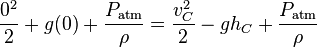
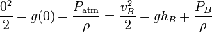
Bernoulli's equation may be applied to a siphon to derive the flow rate and maximum height of the siphon.

- Let the surface of the upper reservoir be the reference elevation.
- Let point A be the start point of siphon, immersed within the higher reservoir and at a depth −d below the surface of the upper reservoir.
- Let point B be the intermediate high point on the siphon tube at height +hB above the surface of the upper reservoir.
- Let point C be the drain point of the siphon at height −hC below the surface of the upper reservoir.
Bernoulli's equation:
-

-
 = fluid velocity along the streamline
 -
 = gravitational acceleration downwards
 -
 = elevation in gravity field
 -
 = pressure along the streamline
 -
 = fluid density
Apply Bernoulli's equation to the surface of the upper reservoir. The surface is technically falling as the upper reservoir is being drained. However, for this example we will assume the reservoir to be infinite and the velocity of the surface may be set to zero. Furthermore, the pressure at both the surface and the exit point C is atmospheric pressure. Thus:
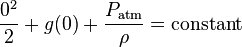 (Equation 1.)
Apply Bernoulli's equation to point A at the start of the siphon tube in the upper reservoir where P = PA, v = vA and y = −d
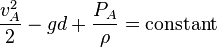 (Equation 2.)
Apply Bernoulli's equation to point B at the intermediate high point of the siphon tube where P = PB, v = vB and y = hB
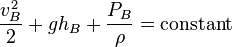 (Equation 3.)
Apply Bernoulli's equation to point C where the siphon empties. Where v = vC and y = −hC. Furthermore, the pressure at the exit point is atmospheric pressure. Thus:
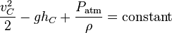 (Equation 4.)
Velocity
As the siphon is a single system, the constant in all four equations is the same. Setting equations 1 and 4 equal to each other gives:
Solving for vC:
- Velocity of siphon:

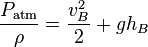
The velocity of the siphon is thus driven solely by the height difference between the surface of the upper reservoir and the drain point. The height of the intermediate high point, hB, does not affect the velocity of the siphon. However, as the siphon is a single system, vB = vC and the intermediate high point does limit the maximum velocity. The drain point cannot be lowered indefinitely to increase the velocity. Equation 3 will limit the velocity to a positive pressure at the intermediate high point to prevent cavitation. The maximum velocity may be calculated by combining equations 1 and 3:
Setting PB = 0 and solving for vmax:
- Maximum velocity of siphon:

The depth, −d, of the initial entry point of the siphon in the upper reservoir, does not affect the velocity of the siphon. No limit to the depth of the siphon start point is implied by Equation 2 as pressure PA increases with depth d. Both these facts imply the operator of the siphon may bottom skim or top skim the upper reservoir without impacting the siphon's performance.
Note that this equation for the velocity is the same as that of any object falling height hC. Note also that this equation assumes PC is atmospheric pressure. If the end of the siphon is below the surface, the height to the end of the siphon cannot be used; rather the height difference between the reservoirs should be used.
Maximum height
Although siphons can exceed the barometric height of the liquid in special circumstances, e.g. when the liquid is degassed and the tube is clean and smooth,[85] in general the practical maximum height can be found as follows.
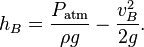
Setting equations 1 and 3 equal to each other gives:
Maximum height of the intermediate high point occurs when it is so high that the pressure at the intermediate high point is zero; in typical scenarios this will cause the liquid to form bubbles and if the bubbles enlarge to fill the pipe then the siphon will "break". Setting PB = 0:
Solving for hB:
- General height of siphon:
This means that the height of the intermediate high point is limited by pressure along the streamline being always greater than zero.
- Maximum height of siphon:
This is the maximum height that a siphon will work. It is where the velocity head and pressure head has been converted to maximum gravitational head. Substituting values will give approximately 10 metres for water and, by definition of standard pressure, 0.76 metres (760 mm or 30 in) for mercury. The ratio of heights (about 13.6) equals the ratio of densities of water and mercury (at a given temperature). Note that as long as this condition is satisfied (pressure greater than zero), the flow at the output of the siphon is still only governed by the height difference between the source surface and the outlet. Volume of fluid in the apparatus is not relevant as long as the pressure head remains above zero in every section. Because pressure drops when velocity is increased, a static siphon (or manometer) can have a slightly higher height than a flowing siphon.
Vacuum siphons
Experiments have shown that siphons can operate in a vacuum, via cohesion and tensile strength between molecules, provided that the liquids are pure and degassed and surfaces are very clean.[7][5][4][6][8][86][87]
Oxford English Dictionary
The Oxford English Dictionary (OED) entry on siphon, published in 1911, states that a siphon works by atmospheric pressure. Stephen Hughes of Queensland University of Technology criticised this in a 2010 article[31] which was widely reported in the media.[88][89][90][91] The OED editors stated, "there is continuing debate among scientists as to which view is correct. ... We would expect to reflect this debate in the fully updated entry for siphon, due to be published later this year."[92] Dr. Hughes continued to defend his view of the siphon in a late September post at the Oxford blog.[93] The 2015 definition by the OED is:
A tube used to convey liquid upwards from a reservoir and then down to a lower level of its own accord. Once the liquid has been forced into the tube, typically by suction or immersion, flow continues unaided.
The Encyclopædia Britannica currently describes a siphon as:
Siphon, also spelled syphon, instrument, usually in the form of a tube bent to form two legs of unequal length, for conveying liquid over the edge of a vessel and delivering it at a lower level. Siphons may be of any size. The action depends upon the influence of gravity (not, as sometimes thought, on the difference in atmospheric pressure; a siphon will work in a vacuum) and upon the cohesive forces that prevent the columns of liquid in the legs of the siphon from breaking under their own weight. At sea level, water can be lifted a little more than 10 metres (33 feet) by a siphon. In civil engineering, pipelines called inverted siphons are used to carry sewage or stormwater under streams, highway cuts, or other depressions in the ground. In an inverted siphon the liquid completely fills the pipe and flows under pressure, as opposed to the open-channel gravity flow that occurs in most sanitary or storm sewers.[94]
See also
| Wikimedia Commons has media related to Siphons. |
- 1992 Guadalajara explosions for details of an accident where a plumbing method Trap (plumbing) also known as a inverted siphon was partially responsible for gas explosions.
- Communicating vessels
- Gravity feed
- Jiggle syphon
References
- ↑ 1.0 1.1 http://iopscience.iop.org/0031-9120/46/4/006/pdf/0031-9120_46_4_006.pdf?origin=publication_detail
- ↑ 2.0 2.1 http://www.phys.uhh.hawaii.edu/documents/TPT-final.pdf
- ↑ 3.0 3.1 http://reu.eng.hawaii.edu/harp/sites/reu.eng.hawaii.edu.harp/files/mcguire_finalpresentation.pdf
- ↑ 4.0 4.1 4.2 Minor, Ralph Smith (1914). "Would a Siphon Flow in a Vacuum! Experimental Answers" (PDF). School Science and Mathematics. 14,2 (2): 152. doi:10.1111/j.1949-8594.1914.tb16014.x.
- ↑ 5.0 5.1 "Video Demonstration of Siphon in Vacuum".
- ↑ 6.0 6.1 Duane1902
- ↑ 7.0 7.1 7.2 7.3 7.4 7.5 http://www.mindspring.com/~rwramette/nokes.pdf
- ↑ 8.0 8.1 Siphon Concepts
- ↑ http://www.brightstorm.com/science/physics/solids-liquids-and-gases/physics-siphoning-torricellis-law/
- ↑ NCEES (2011). Fundamentals of Engineering: Supplied Reference Handbook. Clemson, South Carolina: NCEES. p. 64. ISBN 978-1-932613-59-9.
- ↑ Finnemore, John, E. and Joseph B. Franzini (2002). Fluid Mechanics: With Engineering Applications. New York: McGraw Hill, Inc. pp. 14–29. ISBN 978-0-07-243202-2.
- ↑ http://www.moundtop.com/pdf/AncientWinemaking.pdf
- ↑ http://books.google.com.au/books?id=xuDDqqa8FlwC&q=siphon#v=snippet&q=siphon&f=false
- ↑ Dora P. Crouch (1993). "Water management in ancient Greek cities". Oxford University Press US. p. 119. ISBN 0-19-507280-4
- ↑ http://books.google.com.au/books?id=xuDDqqa8FlwC&q=siphon#v=snippet&q=siphon&f=false
- ↑ http://himedo.net/TheHopkinThomasProject/TimeLine/Wales/Steam/URochesterCollection/Hero/index-2.html
- ↑ Banu Musa (authors), Donald Routledge Hill (translator) (1979). The book of ingenious devices (Kitāb al-ḥiyal). Springer. p. 21. ISBN 90-277-0833-9.
- ↑ http://www.history-science-technology.com/articles/articles%2011.html
- ↑ (Calvert 2000, "Maximum height to which water can be raised by a suction pump")
- ↑ 20.0 20.1 20.2 20.3 20.4 Richert, Alex; Binder, P.-M. (February 2011). "Siphons, Revisited" (PDF). The Physics Teacher 49 (2): 78. Bibcode:2011PhTea..49...78R. doi:10.1119/1.3543576, press release: Yanking the chain on siphon claims, University of Hawaiʻi at Hilo, 19 January 2011
- ↑ 21.0 21.1 21.2 21.3 21.4 "The Great Siphon Definition Debate". Retrieved 31 May 2010.
- ↑ Smith, Andrew M. (1991). "Negative Pressure Generated by Octopus Suckers: A Study of the Tensile Strength of Water in Nature". Journal of Experimental Biology 157 (1): 257–271.
- ↑ Streeter, Victor L., Fluid Mechanics, Section 10.2 (4th edition), McGraw-Hill, New York, USA. Library of Congress Catalog Card No. 66-15605
- ↑ (Calvert 2000, "Maximum height to which water can be raised by a suction pump" and "The siphon")
- ↑ http://iopscience.iop.org/0031-9120/6/5/005/pdf/0031-9120_6_5_005.pdf
- ↑ http://eprints.qut.edu.au/31098/25/A_practical_example_of_a_siphon_at_work_eprint_(2).pdf
- ↑ http://iopscience.iop.org/0031-9120/46/3/007/pdf/0031-9120_46_3_007.pdf
- ↑ http://pubs.acs.org/doi/abs/10.1021/ed2001818
- ↑ http://scitation.aip.org/content/aip/magazine/physicstoday/article/64/8/10.1063/PT.3.1199
- ↑ http://www.nature.com/srep/2014/140422/srep04741/pdf/srep04741.pdf
- ↑ 31.0 31.1 Hughes, Stephen W (2010). "A practical example of a siphon at work" (PDF). Physics Education 45 (2): 162–166. Bibcode:2010PhyEd..45..162H. doi:10.1088/0031-9120/45/2/006A practical example of a siphon at work, supporting website
- ↑ 32.0 32.1 "The Pulley Analogy Does Not Work For Every Siphon".
- ↑ "Material Safety Data Sheet for MidGrade Unleaded Gasoline" (PDF). 28 November 2006.
- ↑ http://www.google.com/patents/US136809?printsec=drawing
- ↑ http://www.google.com/patents/US5358000
- ↑ "Siphons for Geosiphon Treatment Systems". sti.srs.gov. Retrieved 11 May 2010.
- ↑ http://www.caromausa.com/resources/videos/articles25.php
- ↑ http://www.greenbuildingstore.co.uk/page--siphon-vs-valve-debate.html
- ↑ http://www.romanaqueducts.info/picturedictionary/pd_onderwerpen/siphon.htm
- ↑ http://www.thenakedscientists.com/forum/index.php?topic=7636.0
- ↑ http://www.romanaqueducts.info/siphons/siphons.htm
- ↑ http://www.askthebuilder.com/sewer-odors-in-bathroom/
- ↑ http://plumbing.about.com/od/drains/a/Drain-Trap-What-Is-The-Purpose-Of-A-Drain-Trap.htm
- ↑ http://www.aconcordcarpenter.com/how-to-retrieve-an-item-dropped-down-a-sink-drain.html
- ↑ http://www.lmnoeng.com/Channels/InvertedSiphon.htm
- ↑ http://www.azdeq.gov/environ/water/engineering/download/scs_depressed.pdf
- ↑ http://www.grimsby.ca/Water-FAQ-Backflow-Prevention/what-is-back-siphonage-and-its-causes.html
- ↑ http://water.ky.gov/DRINKINGWATER/Pages/BackflowBacksiphonage.aspx
- ↑ 49.0 49.1 http://water.epa.gov/infrastructure/drinkingwater/pws/crossconnectioncontrol/upload/2003_04_09_crossconnection_chapter03.pdf
- ↑ "Toiletology ... Anti-siphon needs an explanation". www.toiletology.com. Retrieved 11 May 2010.
- ↑ http://www.cleaningshop.com.au/contents/en-us/d1569.html
- ↑ Tokoro, Kazuhiko; Chiba, Yasuhiro; Abe, Hiroyuki; Tanaka, Nobumasa; Yamataki, Akira; Kanno, Hiroshi (1994). "Importance of anti-siphon devices in the treatment of pediatric hydrocephalus". Child's Nervous System 10 (4): 236–8. doi:10.1007/BF00301160.
- ↑ "Hydrocephalus and Shunts in the Person with Spina Bifida" (Press release). Spina Bifida Association of America. 2009. Retrieved 9 November 2010.
- ↑ Zemack, Göran; Romner, Bertil (1999). "Seven-year clinical experience with the Codman Hakim programmable valve: a retrospective study of 583 patients". Neurosurgical FOCUS 7 (4): 941–8. doi:10.3171/foc.1999.7.4.11.
- ↑
- ↑ http://www.wika.com.au/910_15_en_co.WIKA
- ↑ http://www.leybold-shop.com/siphon-barometer-31714.html
- ↑ http://www.axinum.com/FAQ.htm
- ↑ http://voronoi.ics.uci.edu/cgi-bin/Dict?Form=Dict2&Database=*&Query=siphoid
- ↑ https://sites.google.com/site/donsairbrushtips/gravity-or-siphon
- ↑ http://physics.kenyon.edu/EarlyApparatus/Fluids/Heros_Fountain/Heros_Fountain.html
- ↑ http://www.xcdsystem.com/iie2014/abstract/finalpapers/i835.pdf
- ↑ Kezerashvili; Sapozhnikov (2003). "Magic Fountain". arXiv:physics/0310039v1 [physics.ed-ph]. More than one of
|author2=and|last2=specified (help) - ↑ 64.0 64.1 http://www.siphonic.com.au/downloads/Siphonic%20Brochure.pdf
- ↑ http://www.fullflow.com/pages/syphonic-explained/
- ↑ 66.0 66.1 http://w3.unisa.edu.au/researcher/issue/2006May/story3.asp
- ↑ http://www.vl-irrigation.org/cms/index.php?id=440&type=7
- ↑ http://www.abc.net.au/local/stories/2008/11/26/2429797.htm
- ↑ http://eprints.qut.edu.au/31098/32/Lake__Bonney_siphon_and_embankment1.JPG
- ↑ http://nptel.ac.in/courses/105106114/pdfs/Unit34/34_1.pdf
- ↑ http://www.tamuc.edu/academics/colleges/scienceengineeringagriculture/departments/engineeringTechnology/documents/safety/Hm16036e.pdf
- ↑ http://www.idosi.org/wasj/wasj14%288%2911/20.pdf
- ↑ Rao, Govinda NS (2008). "Design of Volute Siphon" (PDF). Journal of the Indian Institute of Science 88 (3): 915–930.
- ↑ "Physics Demonstrations - Light". sprott.physics.wisc.edu. Retrieved 11 May 2010.
- ↑ School of Chemistry. Chem.soton.ac.uk. Retrieved on 11 November 2010.
- ↑ Tubeless Siphon and Die Swell Demonstration, Christopher W. MacMinn & Gareth H. McKinley, 26 September 2004
- ↑ Siphon. Grow.arizona.edu. Retrieved on 11 November 2010.
- ↑ http://www.descsite.nl/Publications/Thesis/Gisolf/Gisolf_Chap1.pdf
- ↑ 79.0 79.1 http://ajpregu.physiology.org/content/ajpregu/289/2/R627.full.pdf
- ↑ https://www.ncbi.nlm.nih.gov/pubmed/2916707
- ↑ http://www.ncbi.nlm.nih.gov/pubmed/2890463
- ↑ http://ajpregu.physiology.org/content/ajpregu/289/2/R629.full.pdf
- ↑ http://www.researchgate.net/profile/Aigara_Alves/publication/260247798_Flora_da_Bahia_Siphonocladaceae/links/0a85e5342e37eb90b3000000.pdf
- ↑ http://florabrasiliensis.cria.org.br/search?taxon_id=20627
- ↑ "Water Flowing Up 24 meters Not Magic, Just Science! Gravity of Life (Part3)". Retrieved 30 Nov 2014.
- ↑ Ganci, S; Yegorenkov, V (2008). "Historical and pedagogical aspects of a humble instrument". European Journal of Physics 29 (3): 421–430. Bibcode:2008EJPh...29..421G. doi:10.1088/0143-0807/29/3/003.
- ↑ Nokes M. C. (1948). "Vacuum siphons". Am. J. Phys. 16: 254.
- ↑ QUT physicist corrects Oxford English Dictionary
- ↑ AOL News, For 99 Years, Oxford English Dictionary Got It Wrong
- ↑ Calligeros, Marissa, Dictionary mistake goes unnoticed for 99 years, Brisbane Times, 10 May 2010
- ↑ Malkin, Bonnie, Physicist spots 99-year-old mistake in Oxford English Dictionary, The Daily Telegraph (London), 11 May 2010
- ↑ "On The Definition of "Siphon"". OUPblog. Oxford University Press. 21 May 2010. Retrieved 23 May 2010.
- ↑ http://blog.oup.com/2010/05/siphon/comment-page-1/#comment-177572
- ↑ http://www.britannica.com/EBchecked/topic/546445/siphon
- Calvert, James B. (11 May 2000). "Siphon". Hydrostatics. Retrieved 5 January 2007.