Residual-current device
| Part of a series on |
| Electrical wiring |
|---|
| Regulation of Electrical Installations |
| Wiring Methods |
|
| Circuit Breakers and Devices |
| Electrical Distribution |
| Wiring by Region or Country |

A residual-current device (RCD), or residual-current circuit breaker (RCCB) is an electrical wiring device that disconnects a circuit whenever it detects that the electric current is not balanced between the energized (line) conductor(s) and the return (neutral) conductor. In normal circumstances, these two wires are expected to carry matching currents, and any difference usually indicates a short circuit or other electrical anomaly is present. Even a small leakage current can mean a risk of harm or death due to electric shock if the leaking electric current passes through a human being; a current of around 30mA (0.030 Amps) is potentially sufficient to cause cardiac arrest or serious harm if it persists for more than a small fraction of a second. RCCBs are designed to disconnect the conducting wires quickly enough to prevent serious injury from such shocks. (This is commonly described as the RCD being "tripped".) Injury may still occur in some cases, for example if a person falls after receiving a shock.
A RCD does not provide protection against unexpected or dangerously high current when current is flowing in the usual wires in the circuit, therefore they cannot replace a fuse or protect against overheating or fire risk due to overcurrent (overload) or short circuits if the fault does not lead to current leakage. Therefore RCDs are often used or integrated as a single product along with some kind of circuit breaker, such as a fuse or MCB ("miniature circuit breaker"), which adds protection in the event of excessive current in the circuit. RCDs also cannot detect the situation where a human being accidentally touches both conductors at the same time, since the flow of current through an expected device, an unexpected route, or a human being, are indistinguishable if the current returns through the expected conductor.
RCDs are usually testable and resettable devices. Commonly they include a button that when pressed safely creates a small leakage condition, and a switch that reconnects the conductors when a fault condition has been cleared. Depending upon their design, some RCDs disconnect both the energized and return conductors upon a fault, while others only disconnect the energized conductor, and rely upon the return conductor being at ground (earth) potential. The former are commonly known as "double pole" designs; the latter as "single pole" designs. If the fault has left the return wire "floating", or not at its expected ground potential for any reason, then a single pole RCD model will leave this conductor still connected to the circuit when it detects the fault.
In the United States and Canada, a residual-current device is most commonly known as a Ground Fault Circuit Interrupter (GFCI), Ground Fault Interrupter (GFI) or an Appliance Leakage Current Interrupter (ALCI). In the United Kingdom, a residual-current devices is known as an RCD, and a combined RCD+MCB is known as an RCBO (Residual-current Circuit Breaker with Overcurrent protection). In Australia, they are sometimes known as Safety Switches or an RCD. An earth leakage circuit breaker (ELCB) may be a residual-current device, although an older type of voltage-operated earth leakage circuit breaker also exists.
Purpose and operation

AC-1: imperceptible
AC-2: perceptible but no muscle reaction
AC-3: muscle contraction with reversible effects
AC-4: possible irreversible effects
AC-4.1: up to 5% probability of ventricular fibrillation
AC-4.2: 5-50% probability of fibrillation
AC-4.3: over 50% probability of fibrillation
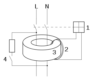
1. Electromagnet with help electronics
2. Current transformer secondary winding
3. Transformer core
4. Test switch
L live conductor
N neutral conductor.

RCDs are designed to disconnect the circuit if there is a leakage current. By detecting small leakage currents (typically 5–30 milliamperes) and disconnecting quickly enough (<300 ms), they may prevent electrocution. They are an essential part of the automatic disconnection of supply (ADS), i.e. to switch off when a fault develops, rather than rely on human intervention, this is one of the essential tenets of modern electrical practice. There are also RCDs with intentionally slower responses and lower sensitivities, designed to protect equipment or avoid starting electrical fires, but not disconnect unnecessarily for equipment which has greater leakage currents in normal operation. To prevent electrocution, RCDs should operate within 25-40 milliseconds with any leakage currents (through a person) of greater than 30 milliamperes, before electric shock can drive the heart into ventricular fibrillation, the most common cause of death through electric shock. By contrast, conventional circuit breakers or fuses only break the circuit when the total current is excessive (which may be thousands of times the leakage current an RCD responds to). A small leakage current, such as through a person, can be a very serious fault, but would probably not increase the total current enough for a fuse or circuit breaker to break the circuit, and certainly not to do so fast enough to save a life.
RCDs operate by measuring the current balance between two conductors using a differential current transformer. This measures the difference between current flowing through the live conductor and that returning through the neutral conductor. If these do not sum to zero, there is a leakage of current to somewhere else (to earth/ground, or to another circuit), and the device will open its contacts. Operation does not require a fault current to return via the earth wire in the installation; the trip will operate just as well if the return path is via plumbing, contact with terra firma or any other current path. Automatic disconnection and a measure of shock protection is therefore still provided even if the earth wiring of the installation is damaged or incomplete.
Residual current detection is complementary to over-current detection. Residual current detection cannot provide protection for overload or short-circuit currents, except for the special case of a short circuit from live to ground (not live to neutral).
For a RCD used with three-phase power, all three live conductors and the neutral (if fitted) must pass through the current transformer.
Typical design


The diagram depicts the internal mechanism of a residual-current device (RCD). The device pictured is designed to be wired in-line in an appliance power cord. It is rated to carry a maximum current of 13 amperes and is designed to trip on a leakage current of 30 mA. This is an active RCD; that is, it latches electrically and therefore trips on power failure, a useful feature for equipment that could be dangerous on unexpected re-energisation. Some early RCDs were entirely electromechanical and relied on finely balanced sprung over-centre mechanisms driven directly from the current transformer. As these are hard to manufacture to the required accuracy, and prone to drift in sensitivity both from pivot wear and lubricant dry-out, the electronically amplified type with a more robust solenoid part as illustrated are now dominant.
The incoming supply and the neutral conductors are connected to the terminals at (1) and the outgoing load conductors are connected to the terminals at (2). The earth conductor (not shown) is connected through from supply to load uninterrupted. When the reset button (3) is pressed the contacts ((4) and hidden behind (5)) close, allowing current to pass. The solenoid (5) keeps the contacts closed when the reset button is released.
The sense coil (6) is a differential current transformer which surrounds (but is not electrically connected to) the live and neutral conductors. In normal operation, all the current down the live conductor returns up the neutral conductor. The currents in the two conductors are therefore equal and opposite and cancel each other out.
Any fault to earth (for example caused by a person touching a live component in the attached appliance) causes some of the current to take a different return path which means there is an imbalance (difference) in the current in the two conductors (single phase case), or, more generally, a nonzero sum of currents from among various conductors (for example, three phase conductors and one neutral conductor).
This difference causes a current in the sense coil (6) which is picked up by the sense circuitry (7). The sense circuitry then removes power from the solenoid (5) and the contacts (4) are forced apart by a spring, cutting off the electricity supply to the appliance.
The device is designed so that the current is interrupted in milliseconds, greatly reducing the chances of a dangerous electric shock being received.
The test button (8) allows the correct operation of the device to be verified by passing a small current through the orange test wire (9). This simulates a fault by creating an imbalance in the sense coil. If the RCD does not trip when this button is pressed then the device must be replaced.
RCD with additional overcurrent protection circuitry (RCBO or GFCI)
Residual-current and overcurrent protection may be combined in one device for installation into the service panel; this device is known as a GFCI breaker (Ground Fault Circuit Interrupter) in the USA and Canada, and as an RCBO (residual-current circuit breaker with overload protection) in Europe. In the US, RCBOs are more expensive than RCD outlets.
As well as requiring both line and neutral (or 3-phase) input and output, many GFCI/RCBO devices require a functional earth (FE) connection, this serves to provide both EMC immunity and to reliably operate the device if the input side neutral connection is lost but live and earth remain.
For reasons of space many devices, especially in DIN rail format use flying leads rather than screw terminals, especially for the neutral input and FE connections. Additionally, because of the small form factor, the output cables of some models (Eaton/MEM) are used to form the primary winding of the RCD part and the outgoing circuit cables must be led through a specially dimensioned terminal tunnel with the current transformer part around it. This can lead to incorrect failed trip results when testing with meter probes from the screw heads of the terminals, rather than from the final circuit wiring.
More than one RCD feeding another is unnecessary, provided they have been wired properly. One exception is the case of a TT earthing system where the earth loop impedance may be high, meaning that a ground fault might not cause sufficient current to trip an ordinary circuit breaker or fuse. In this case a special 100 mA (or greater) trip current time-delayed RCD is installed covering the whole installation and then more sensitive RCDs should be installed downstream of it for sockets and other circuits which are considered high risk.
-

CHINT's RCBO
-
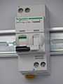
Schneider Electric
-
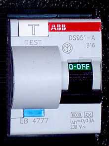
ABB
Common features and variations
Number of poles and pole terminology
The number of poles represents the number of conductors that will be interrupted if a fault condition occurs. RCDs used on single phase AC supplies (two current paths) such as domestic power, are usually one or two pole designs, also known as single and double pole. A single pole RCD interrupts only the energized conductor, while a double pole RCD interrupts both the energized and return conductors. (In a single pole RCD, the return conductor is usually anticipated to be at ground potential at all times, and therefore safe on its own, however see limitations below).
RCDs with three or more poles can be used on three phase AC supplies (three current paths) or to disconnect an earth conductor as well, with four pole RCDs used to interrupt three phase + neutral supplies. Specially designed RCDs can also be used with both AC and DC power distribution systems.
The following terms are sometimes used to describe the manner in which conductors are connected and disconnected by an RCD:
- Single pole / SP / one pole - the RCD will disconnect the energized wire only.
- Double pole / DP / two pole - the RCD will disconnect both the energized and return wires.
- 1+N and 1P+N - non standard terms used in the context of RCBOs, at times used differently by different manufacturers. Typically these terms may signify that the return (neutral) conductor is an isolating pole only, without a protective element (an unprotected but switched neutral), or that the RCBO provides a conducting path and connectors for the return (neutral) conductor but this path will remain uninterrupted if a fault occurs (sometimes known as "solid neutral"),[2] or that both conductors will disconnect for some faults (such as RCD detected leakage) but only one conductor will disconnect for other faults (such as overload).[3]
Maximum rated current
The rated current of an RCD is chosen according to the maximum sustained load current it is expected to carry, so generally if the RCD is connected in series with a single fuse or circuit-breaker, the rated current of the RCD shall be at least the same as the fuse or circuit breaker, though in the case of an RCD feeding many circuit breakers, an allowance for load diversity may or may not be permissible depending on the type of load expected.
Sensitivity
RCD sensitivity is expressed as the rated residual operating current, noted IΔn. Preferred values have been defined by the IEC, thus making it possible to divide RCDs into three groups according to their IΔn value.
- High sensitivity (HS): 6 – 10 – 30 mA (for direct-contact / life injury protection)
- Medium sensitivity (MS): 100 – 300 – 500 – 1,000 mA (for fire protection)
- Low sensitivity (LS): 3 – 10 – 30 A (typically for protection of machine)
Note that the nominal value of residual current indicated above is not an absolute value. More information is presented below.
Break time (response speed)
There are two groups of devices:
- G (general use) for instantaneous RCDs (i.e., without a time delay).
- Minimum break time: immediate
- Maximum break time: 200 ms for 1× IΔn, 150 ms for 2× IΔn, and 40 ms for 5× IΔn
- S (selective) or T (time delayed) for RCDs with a short time delay (typically used in circuits containing surge suppressors)
- Minimum break time: 130 ms for 1× IΔn, 60 ms for 2× IΔn, and 50 ms for 5× IΔn
- Maximum break time: 500 ms for 1× IΔn, 200 ms for 2× IΔn, and 150 ms for 5× IΔn
Type, or mode (types of current leakage issue detected)
Standard IEC 60755 (General requirements for residual current operated protective devices) defines three types of RCD depending on the characteristics of the fault current.
- Type AC: RCD for which tripping is ensured
- for residual sinusoidal alternating currents
- Type A: RCD for which tripping is ensured
- as for type AC
- for residual pulsating direct currents
- for residual pulsating direct currents superimposed by a smooth direct current of 6 mA, with or without phase-angle control, independent of the polarity
- Type B: RCD for which tripping is ensured
- as for type A
- for residual sinusoidal currents up to 1 kHz
- for residual sinusoidal currents superposed by a pure direct current
- for pulsating direct currents superposed by a pure direct current
- for residual currents which may result from rectifying circuits
- three pulse star connection or six pulse bridge connection
- two pulse bridge connection line-to-line with or without phase-angle monitoring, independently of the polarity
Surge current resistance
The surge current refers to the peak current an RCD is designed to withstand using a test impulse of specified characteristics (an 8/20 µs impulse, named after the time constants of the rise and fall of current).
The IEC 61008 and IEC 61009 standards impose the use of a 0.5 µs/ 100 kHz damped oscillator wave (ring wave) to test the ability of residual-current protection devices to withstand operational discharges with a peak current equal to 200 A. With regard to atmospheric discharges, IEC 61008 and 61009 standards establish the 8/20 µs surge current test with 3 kA peak current but limit the requirement to RCDs classified as Selective.
Form factor (physical format)
A ground fault circuit interrupter circuit breaker (GFCI in USA and Canada) and residual-current breaker with overload (RCBO in Europe) are devices which combine the functions of a residual-current device with a circuit breaker. They detect both supply imbalance and overload current.
In Europe, RCDs can fit on the same DIN rail as the MCBs, however the busbar arrangements in consumer units and distribution boards can make it awkward to use them in this way. If it is desired to protect an individual circuit, an RCBO (Residual-current Circuit Breaker with Overcurrent protection) can be used. This incorporates an RCD and a miniature circuit breaker in one device.
Electrical plugs which incorporate an RCD are sometimes installed on appliances which might be considered to pose a particular safety hazard, for example long extension leads which might be used outdoors or garden equipment or hair dryers which may be used near a bath or sink. Occasionally an in-line RCD may be used to serve a similar function to one in a plug. By putting the RCD in the extension lead, protection is provided at whatever outlet is used even if the building has old wiring, such as knob and tube, or wiring that does not contain a grounding conductor.
In North America, GFI receptacles can be used in cases where there is no grounding conductor, but must be labeled as "Ungrounded". An ungrounded GFI receptacle will trip using the built in Test button, but will not trip using a GFI test plug, because the plug tests by shorting a small current from line to the non existent ground.
Electrical sockets with included RCDs are becoming common.
Testing of correct operation
RCDs can be tested with built-in test button to confirm functionality on a regular basis. RCDs if wired improperly may not operate correctly and are generally tested by the installer to verify correct operation. Use of a solenoid voltmeter from live to earth provides an external path and can test the wiring to the RCD. Such a test may be performed on installation of the device and at any "downstream" outlet.
Limitations
A residual-current circuit breaker cannot remove all risk of electric shock or fire. In particular, an RCD alone will not detect overload conditions, phase to neutral short circuits or phase-to-phase short circuits (see three-phase electric power). Over-current protection (fuses or circuit breakers) must be provided. Circuit breakers that combine the functions of an RCD with overcurrent protection respond to both types of fault. These are known as RCBOs, and are available in 2, 3 and 4 pole configurations. RCBOs will typically have separate circuits for detecting current imbalance and for overload current but will have a common interrupting mechanism.
An RCD will help to protect against electric shock where current flows through a person from a phase (live / line / hot) to earth. It cannot protect against electric shock where current flows through a person from phase to neutral or phase to phase, for example where a finger touches both live and neutral contacts in a light fitting; a device can not differentiate between current flow through an intended load from flow through a person, though the RCD may still trip if the person is in contact with the ground (earth) as some current will still pass through the persons finger and body to earth.
Whole installations on a single RCD, common in older installations in the UK, are prone to 'nuisance' trips that can cause secondary safety problems with loss of lighting and defrosting of food. Frequently the trips are caused by deteriorating insulation on heater elements such as water heaters and cooker elements or rings. Although regarded as a nuisance the fault is with the deteriorated element and not the RCD: replacement of the offending element will resolve the problem; replacing the RCD will not.
In the case of RCDs that need a power supply, a dangerous condition can arise if the neutral wire is broken or switched off on the supply side of the RCD, while the corresponding live wire remains uninterrupted. The tripping circuit needs power to work and does not trip when the power supply fails. Connected equipment will not work without a neutral, but the RCD cannot protect people from contact with the energized wire. For this reason circuit breakers must be installed in a way that ensures that the neutral wire cannot be switched off unless the live wire is also switched off at the same time. Where there is a requirement for switching off the neutral wire, two-pole breakers (or four-pole for 3-phase) must be used. To provide some protection with an interrupted neutral, some RCDs and RCBOs are equipped with an auxiliary connection wire that must be connected to the earth busbar of the distribution board. This either enables the device to detect the missing neutral of the supply, causing the device to trip, or provides an alternative supply path for the tripping circuitry, enabling it to continue to function normally in the absence of the supply neutral.
Related to this, a single (one) pole RCD/RCBO interrupts the energized conductor only, while a double (two) pole device interrupts both the energized and return conductors. Usually this is a standard and safe practice since the return conductor is held at ground potential anyway. However because of its design, a single pole RCD will not isolate or disconnect all relevant wires in certain uncommon situations, for example where the return conductor is not being held as expected, at ground potential, or where current leakage occurs between the return and earth conductors. In these cases, a double pole RCD will offer protection since the return conductor would also be disconnected.
History and nomenclature
The world’s first high-sensitivity earth leakage protection system (i.e. a system capable of protecting people from the hazards of direct contact between a live conductor and earth), was a second-harmonic magnetic amplifier core-balance system, known as the magamp, developed in South Africa by Henri Rubin. Electrical hazards were of great concern in South African gold mines, and Rubin, an engineer at the company F.W.J. Electrical Industries, initially developed a cold-cathode system in 1955 which operated at 525 V and had a tripping sensitivity of 250 mA. Prior to this, core balance earth leakage protection systems operated at sensitivities of about 10 A.
The cold cathode system was installed in a number of gold mines and worked reliably. However, Rubin began working on a completely novel system with greatly improved sensitivity, and by early 1956, he had produced a prototype second-harmonic magnetic amplifier-type core balance system (South African Patent No. 2268/56 and Australian Patent No. 218360). The prototype magamp was rated at 220 V, 60 A and had an internally adjustable tripping sensitivity of 12.5–17.5 mA. Very rapid tripping times were achieved through a novel design, and this combined with the high sensitivity was well within the safe current-time envelope for ventricular fibrillation determined by Charles Dalziel of the University of California, Berkeley, USA, who had estimated electrical shock hazards in humans. This system, with its associated circuit breaker, included overcurrent and short-circuit protection. In addition, the original prototype was able to trip at a lower sensitivity in the presence of an interrupted neutral, thus protecting against an important cause of electrical fire.
Following the accidental electrocution of a woman in a domestic accident at the Stilfontein gold mining village near Johannesburg, a few hundred F.W.J. 20 mA magamp earth leakage protection units were installed in the homes of the mining village during 1957 and 1958. F.W.J. Electrical Industries, which later changed its name to FW Electrical Industries, continued to manufacture 20 mA single phase and three phase magamp units.
At the time that he worked on the magamp, Rubin also considered using transistors in this application, but concluded that the early transistors then available were too unreliable. However, with the advent of improved transistors, the company that he worked for and other companies later produced transistorized versions of earth leakage protection.
In 1961, Dalziel, working with Rucker Manufacturing Co., developed a transistorized device for earth leakage protection which became known as a Ground Fault Circuit Interrupter (GFCI), sometimes colloquially shortened to Ground Fault Interrupter (GFI). This name for high-sensitivity earth leakage protection is still in common use in the U.S.A.[4][5][6][7][8]
In the early 1970s most North American GFCI devices were of the circuit breaker type. GFCIs built into the outlet receptacle became commonplace beginning in the 1980s. The circuit breaker type, installed into a distribution panel, suffered from accidental trips mainly caused by poor or inconsistent insulation on the wiring. False trips were frequent when insulation problems were compounded by long circuit lengths. So much current leaked along the length of the conductors' insulation that the breaker might trip with the slightest increase of current imbalance. The migration to outlet receptacle based protection in North American installations reduced the accidental trips and provided obvious verification that wet areas were under electrical code-required protection. European installations continue to use primarily RCDs installed at the distribution board, which provides protection in case of damage to fixed wiring; In Europe socket-based RCDs are primarily used for retro-fitting.
Regulation and adoption
Regulations differ widely from country to country. In most countries, not all circuits in a home are protected by RCDs. If a single RCD is installed for an entire electrical installation, any fault may cut all power to the premises.
Australia
In Australia and New Zealand, residual current devices have been mandatory on power circuits since 1991 and on light circuits since 2000.[9] A miniumum of two RCDs is required per domestic installation. All socket outlets and lighting circuits are to be distributed over circuit RCD's.A maximum of three subcircuits only, may be connected to a single RCD.
Austria
Austria regulated residual current devices in the ÖVE E8001-1/A1:2013-11-01 norm (most recent revision). It has been required in private housing since 1980. The maximum activation time must not exceed 0.4 seconds. It needs to be installed on all circuits with power plugs with a maximum leakage current of 30mA and a maximum rated current of 16 A. [10]
Additional requirements are placed on circuits in wet areas, construction sites and commercial buildings.
Belgium
Belgian domestic installations are required to be equipped with a 300 mA residual current device that protects all circuits. Furthermore, at least one 30 mA residual current device is required that protects all circuits in "wet rooms" (e.g. bathroom, kitchen) as well as circuits that power certain "wet" appliances (washing machine, tumble dryer, dishwasher). Electrical underfloor heating is required to be protected by a 100 mA RCD. These RCDs must be of type A.
Brazil
Since NBR 5410 (1997) residual current devices and grounding are required for new construction or repair in wet areas, outdoor areas, interior outlets used for external appliances, or in areas where water is more probable like bathrooms and kitchens.[11]
Denmark
Denmark requires 30 mA RCDs on all circuits that are rated for less than 20 A (circuits at greater rating are mostly used for distribution). This was first introduced in 1975 for new buildings, and then for all buildings in 2008.
Germany
Since May, 1st 1984 RCDs are mandatory for all rooms with a bath tub or a shower. Since June 2007 Germany requires the use of RCDs with no more than 30 mA on sockets up to 20 A which are for general use. (DIN VDE 0100-410 Nr. 411.3.3).
Italy
The Italian law (n. 46 March 1990) prescribes RCDs with no more than 30 mA residual current (informally called "salvavita"—life saver) for all domestic installations to protect all the lines. The law was recently updated to mandate at least two separate RCDs for separate domestic circuits. Magnetic and thermal protection has been compulsory since 1968.
New Zealand
From January 2003, all new circuits originating at the switchboard supplying lighting or socket outlets (power points) in domestic buildings must have RCD protection. Residential facilities (such as boarding houses, hospitals, hotels and motels) will also require RCD protection for all new circuits originating at the switchboard supplying socket outlets. These RCDs will normally be located at the switchboard. They will provide protection for all electrical wiring and appliances plugged into the new circuits.[12]
North America

In North America, RCD (“GFCI”) receptacles invariably have rectangular faces and accept so-called decora face plates. GFCI outlets can be mixed with regular outlets or with switches in a multigang box with a standard cover plate. Arc-fault circuit interrupters (AFCI) are required by current NEC code in locations such as sleeping rooms and incorporate GF protection. As a result, the slightly more expensive GFCI circuit breakers for load centers are less commonly used in residential applications.
In Canada and the United States, two-wire (ungrounded) (NEMA-1) outlets may be replaced with GFCIs to protect against electrocution, and a grounding wire does not need to be supplied to that GFCI. The outlet must be labeled as such. The GFCI manufacturers provide tags for the appropriate installation description. GFCI receptacles can be connected to also protect all the downstream receptacles on that circuit.
GFCI devices approved for protection against electric shock trip at 5 mA within 25 ms. A GFCI device which protects equipment (not people) is allowed to trip as high as 30 mA of current; this is known as an Equipment Protective Device (EPD). "RCDs" with trip currents as high as 500 mA are sometimes deployed in environments (such as computing centers) where a lower threshold would carry an unacceptable risk of accidental trips. These high-current RCDs serve for equipment and fire protection instead of protection against the risks of electrical shocks.
GFCI outlets are required by code in most places where an easy path to ground exists, such as wet areas, rooms with uncovered concrete floors and outdoor areas. In the U.S., successive editions of the National Electrical Code required GFCIs for additional areas: underwater swimming pool lights (1968); construction sites (1974); bathrooms and outdoor areas (1975); garages (1978); near hot tubs or spas (1981); hotel bathrooms (1984); kitchen counter receptacles (1987); crawl spaces and unfinished basements (1990); wet bar sinks (1993); and laundry sinks (2005).[13]
In the United States, the American Boat and Yacht Council requires both GFCI's for outlet and Equipment Leakage Circuit Interrupters (ELCI) for the entire boat. The difference is GFCIs trip on 5mA of current whereas ELCIs trip on 30mA after up to 100 ms. The greater values are intended to provide protection while minimizing nuisance trips. [14]
Norway
In Norway, it has been required in all new homes since 2002, and on all new sockets since 2006.
Turkey
Turkey requires the use of RCDs with no more than 30 mA and 300 mA in all new homes since 2004. This rule was introduced in RG-16/06/2004-25494 .[15]
United Kingdom
The previous 16th Edition of the IEE Electrical Wiring Regulations required use of RCDs for socket outlets that were liable to be used by outdoor appliances. Normal practice in domestic installations was to use a single RCD to cover all the circuits requiring RCD protection (typically sockets and showers) but to have some circuits (typically lighting) not RCD protected. This was to avoid a potentially dangerous loss of lighting should the RCD trip. Protection arrangements for other circuits varied. To implement this arrangement it was common to install a consumer unit incorporating an RCD in what is known as a split load configuration, where one group of circuit breakers is supplied direct from the main switch (or time delay RCD in the case of a TT earth) and a second group of circuits is supplied via the RCD. This arrangement had the recognised problems that cumulative earth leakage currents from the normal operation of many items of equipment could cause spurious tripping of the RCD, and that tripping of the RCD would disconnect power from all the protected circuits.
The current edition (17th) of the regulations requires that all socket outlets in most domestic installations have RCD protection, though there are exemptions. Cables buried in walls must also be RCD protected (again with some specific exemptions). {Refer to 17th Edition Amendment 1 effective from January 2012} Provision of RCD protection for circuits present in bathrooms and shower rooms reduces the requirement for supplementary bonding in those locations. Two RCDs may be used to cover the installation, with upstairs and downstairs lighting and power circuits spread across both RCDs. When one RCD trips, power is maintained to at least one lighting and power circuit. Other arrangements, such as the use of RCBOs, may be employed to meet the regulations. The new requirements for RCDs do not affect most existing installations unless they are rewired, the distribution board is changed, a new circuit is installed, or alterations are made such as additional socket outlets or new cables buried in walls.
RCDs used for shock protection must be of the 'immediate' operation type (not time-delayed) and must have a residual current sensitivity of no greater than 30 mA.
If it can be shown that spurious tripping would cause a greater problem than the risk of the electrical accident the RCD is supposed to prevent (examples might be a supply to a critical factory process, or to life support equipment), RCDs may be omitted, providing affected circuits are clearly labelled and the balance of risks considered, this may include the provision of alternative safety measures.
See also
- Insulation monitoring device
- Domestic AC power plugs and sockets
References
- ↑ Weineng Wang, Zhiqiang Wang, Xiao Peng, Effects of the Earth Current Frequency and Distortion on Residual Current Devices, Scientific Journal of Control Engineering, Dec 2013, Vol 3 Issue 6 pp 417-422
- ↑ explanation on voltimum.com.au, by specialist Ian Richardson]
- ↑ http://docs-asia.electrocomponents.com/webdocs/01e3/0900766b801e3b4d.pdf (states that there is "2 pole switching of phase [energized] and neutral [return]", but then only identifies the energized conductor as being protected against "overloads and short circuits")
- ↑ Charles F. Dalziel, Transistorized ground-fault interrupter reduces shock hazard, IEEE Spectrum, January 1970
- ↑ The Professional Engineer, Official Journal of the Federation of Societies of Professional Engineers of South Africa, pp 67, Vol 6(2) 1977
- ↑ Earl W. Roberts, Overcurrents and Undercurrents – All about GFCIs: Electrical Safety Advances through Electronics, Mystic Publications, Mystic CT, 1996
- ↑ Edward L. Owen, Power System Grounding Part II: RCD & GFCI, IEEE Industry Applications Magazine, July/August 1996
- ↑ Forging ahead: South Africa’s Pioneering Engineers, G R Bozzoli, Witwatersrand University Press, 1997
- ↑ SAA Wiring Rules AS/NZS 3000:2007, Including Amendments 1 & 2, SAI Global Limited
- ↑ ÖVE E8001-1/A1:2013-11-01
- ↑ "Quando o uso do DR é obrigatório". Retrieved 2014-07-23.
- ↑ Residual current devices - ACC by Ministry of Consumer Affairs’ Energy Safety Service (ACC Website, December 2002 ISBN 0-478-26322-8)
- ↑ "GFCIs Fact Sheet". US Consumer Product Safety Commission. Retrieved 2009-06-28.
- ↑ Gropper; Criner (1 September 2010). "Microsoft Word - ELCI White Paper September 1 2010.DOC". Paneltronics, Inc. Retrieved 16 March 2015.
- ↑ , Procedure of Electrical Installation Projects
External links
| Wikimedia Commons has media related to Residual current devices. |