Reflectron

A reflectron (mass reflectron) is a type of time-of-flight mass spectrometer (TOF MS) that comprises a pulsed ion source, field-free region, ion mirror, and ion detector and uses a static or time dependent electric field in the ion mirror to reverse the direction of travel of the ions entering it. Using the reflectron, one can substantially diminish a spread of flight times of the ions with the same mass-to-charge ratio (m/z) caused by spread in kinetic energy of these ions measured at the exit from the ion source.
Development
The idea of improving mass resolution in TOF MS by implementing the reflection of ions from a region with retarding electric field (the ion mirror) has been first proposed by Russian scientist S. G. Alikhanov.[1] In 1973, the dual-stage reflectron utilizing an ion mirror with two regions of homogeneous field was built in a laboratory of Boris Aleksandrovich Mamyrin.[2][3] Mass resolution of the reflectron measured over broad mass range is much larger than that in a simpler (so-called linear) time-of-flight mass spectrometer comprising a pulsed ion source, flight tube, and ion detector. The masses of ions analyzed in the reflectron can span from a few Dalton to a few million Dalton. Sensitivity in the reflectron used for the analysis of ions produced in vacuum by photo or electron ionization, e.g., matrix-assisted laser desorption/ionization source, can be lower than in linear TOF MS due to post-source decay - a dissociation of vibrationally-excited molecular ions (often referred as metastable ions).
Single-stage reflectron
A single-stage reflectron is equipped with an ion mirror that has a single electric field region. The distribution of electric potential along the central axis of the ion mirror can be linear or non-linear. Also, the electric field in the mirror can be constant or time-dependent. In single-stage reflectrons with homogeneous field, a zero field in a field-free region of a flight tube and the homogeneous field inside the ion mirror are separated by highly transparent (~95%) metal grid. The grid position is then referred as the entrance (exit) to the ion mirror and is used to calculate the retarding electric field. The single-stage reflector utilizing homogeneous field can be used to attain high mass resolution in cases where the variation of energies of ions leaving the ion source is small (typically less than a few per cent). Time of flight t of the ions with mass m, charge q, kinetic energy U is
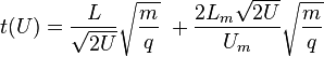
where L is the path length of the ions in a field-free space, Lm is the length of ion mirror, Um is the voltage applied across the mirror. To find a first-order compensation condition for flight time t with respect to spread dU in ion energy U, the following condition should be fulfilled

Assume that the kinetic energy of the ions in the field-free region equals the ion potential energy near the stop point of the ions inside the mirror (we assume that this stop point is very close to the back electrode of the mirror, i.e. Um = U). From here it follows that

In practice, the mirror length should be 10-20% longer to accommodate all ions whose kinetic energy is spread over some interval.
So, the electric field Em in the mirror of a single-stage reflector should be

In case of a wider variation of dU, the relative width of the time-of-flight peaks dt/t in such a reflectron is determined by the uncompensated part of the flight time t(U) proportional to the second derivative
 .
.
where k is a constant depending on the parameters of the single-stage reflector.
Dual-stage reflectron
The mirror in a dual-stage reflectron has two regions (stages) with different fields. This makes it possible to zero both the first and second derivatives of t(U) with respect to energy U. That is why dual-stage reflectrons can compensate flight times over larger variations in ion kinetic energy compared to single-stage ones. This type of reflectrons is typically employed in orthogonal acceleration (oa) TOF MS. "Classic" (Mamyrin's) design includes two highly transparent conductive grids separating regions with homogeneous fields. Mass resolution in dual-stage reflectron is mainly determined by ion scattering on the grids,[4] the spread of kinetic energy of ions leaving the pulsed ion source, and accuracy of mechanical alignment. To diminish effect of scattering, the length of the first deceleration region should be relatively large. Ion scattering makes using triple- and further stage reflectrons impractical.
The effect of ion scattering on mass resolution in single- and dual-stage reflectrons can be diminished by utilizing polarized grid geometry.[5]
Gridless reflectron
One design of gridless reflectron utilizes a "curved-field" ion mirror where the electric potential V(x) along the mirror axis depends non-linearly on distance x to the mirror entrance. Time of flight compensation for ions with different kinetic energy can be obtained by adjusting voltage on the elements producing the electric field inside the mirror, which values follow the equation of an arc of a circle: R2 = V(x)2 + kx2, where k and R are some constants.[6][7]
The electric potential in the mirror of a "quadratic-field" reflectron is proportional to a square of a distance x to the mirror entrance: V(x)= kx2 thus exhibiting a case of one-dimensional harmonic field. If both the ion source and the detector are placed at the mirror entrance and if the ions travel in a close proximity of the ion mirror axis, the flight time of ions in this "quadratic-field" reflectron are almost independent on ion kinetic energy.[8]
A gridless reflectron with nonlinear field, which design comprising only three elements was also demonstrated.[9] Bergmann et al [10] implemented numerical approach to finding voltage distribution across the stack of the metal electrodes as in Fig. 1. that allowed one to create a nonlinear field in different regions of the mirror to provide conditions for efficient compensation of flight times caused by the spread of ion kinetic energies for different entry angles of the ion beam.
Post-source decay
A post-source decay (PSD) is a process specific to the ion source utilizing matrix-assisted laser desorption/ionization and operating in vacuum. In the post-source decay, parent ions (typically of several keV kinetic energy) fragment in a process of laser-induced fragmentation or high-energy collision-induced dissociation (HE CID). Time interval suitable for observation of the post-source decay in the reflectron starts after the precursors (parent ions) leave the ion source and ends prior to the moment when the precursors enter the ion mirror.[11] The kinetic energy of fragment ions of mass m in the post-source decay significantly differs from that of parent ions of mass M and is proportional to m/M. So, the distribution of kinetic energies for the PSD ions is extremely large. Not surprisingly, it cannot be compensated in "classic" single or double-stage reflectrons. To achieve acceptable mass resolution for PSD ions which masses typically distributed over broad mass range, these ions are accelerated to energies substantially (at least, a factor of 4 [12]) exceeding the initial energy of precursor ions. Use of gridless curved-field mirror or that with time-dependent field also improves the mass resolution for fragment ions generated in the post-source decay.
References
- ↑
- Alikhanov, S. G. (1957). "A new impulse technique for ion mass measurement". Sov. Phys. JETP 4: 452.
- ↑
- Mamyrin, B. A.; Karataev, V. I.; Shmikk, D. V.; Zagulin, V. A. (1973). "The mass-reflectron, a new nonmagnetic time-of-flight mass spectrometer with high resolution". Sov. Phys. JETP 37: 45.
- ↑ Mamyrin, Boris (2001-03-22), "Time-of-flight mass spectrometry (concepts, achievements, and prospects)", International Journal of Mass Spectrometry 206 (3): 251–266, doi:10.1016/S1387-3806(00)00392-4.
- ↑
- Bergmann, T.; Martin, T. P.; Schaber, H. (1989). "High‐resolution time‐of‐flight mass spectrometers: Part I. Effects of field distortions in the vicinity of wire meshes". Rev. Sci. Instrum 60: 347. doi:10.1063/1.1140436.
- ↑
- D.S. Selby, V. Mlynski, M. Guilhaus, Demonstrating the effect of the ‘polarised grid geometry’ for orthogonal acceleration time-of-flight mass spectrometers, Rapid Communications in Mass Spectrometry, 14(7), 616 (2000).
- ↑ Cornish, Timothy J.; Cotter, RJ (1993), "A curved-field reflectron for improved energy focusing of product ions in time-of-flight mass spectrometry", Rapid Communications in Mass Spectrometry 7 (11): 1037, doi:10.1002/rcm.1290071114, PMID 8280914
- ↑ Cotter, R.; Iltchenko, S; Wang, D (2005), "The curved-field reflectron: PSD and CID without scanning, stepping or lifting", International Journal of Mass Spectrometry 240 (3): 169, Bibcode:2005IJMSp.240..169C, doi:10.1016/j.ijms.2004.09.022
- ↑ Flensburg, J.; Haid, D; Blomberg, J; Bielawski, J; Ivansson, D (2004), "Applications and performance of a MALDI-TOF mass spectrometer with quadratic field reflectron technology", Journal of Biochemical and Biophysical Methods 60 (3): 319, doi:10.1016/j.jbbm.2004.01.010, PMID 15345299
- ↑
- Zhang J, Enke CG. Simple cylindrical ion mirror with three elements,J Am Soc Mass Spectrom. 11(9), 759 (2000)
- ↑
- T. Bergmann, T. P. Martin, H. Schaber, High resolution time‐of‐flight mass spectrometers. Part III. Reflector design, Rev. Sci. Instrum. 61, 2592 (1990)
- ↑ Kaufmann, R.; Kirsch, D.; Spengler, B. (1994), "Sequenching of peptides in a time-of-flight mass spectrometer: evaluation of postsource decay following matrix-assisted laser desorption ionisation (MALDI)", International Journal of Mass Spectrometry and Ion Processes 131: 355, Bibcode:1994IJMSI.131..355K, doi:10.1016/0168-1176(93)03876-N
- ↑
- Kurnosenko S, Moskovets E., On the high-resolution mass analysis of the product ions in tandem time-of-flight (TOF/TOF) mass spectrometers using a time-dependent re-acceleration technique, Rapid Commun Mass Spectrom 24(1) 63-74, (2010)
Further reading
- Cotter, Robert J. (1994), Time-of-flight mass spectrometry, Columbus, OH: American Chemical Society, ISBN 0-8412-3474-4