Quasi-phase-matching
Quasi-phase-matching is a technique in nonlinear optics which allows a positive net flow of energy from the pump frequency to the signal and idler frequencies by creating a periodic structure in the nonlinear medium. Momentum is conserved, as is necessary for phase-matching, through an additional momentum contribution corresponding to the wavevector of the periodic structure. Consequently, in principle any three-wave mixing process that satisfies energy conservation can be phase-matched. For example, all the optical frequencies involved can be collinear, can have the same polarization, and travel through the medium in arbitrary directions. This allows one to use the largest nonlinear coefficient of the material in the nonlinear interaction.
Quasi-phase-matching ensures that there is positive energy flow from the pump frequency to signal and idler frequencies even though all the frequencies involved are not phase locked with each other. Energy will always flow from pump to signal as long as the phase between the two optical waves is less than 180 degrees. Beyond 180 degrees, energy flows back from the signal to the pump frequencies. The coherence length is the length of the medium in which the phase of pump and the sum of idler and signal frequencies are 180 degrees from each other. At each coherence length the crystal axes are flipped which allows the energy to continue to positively flow from the pump to the signal and idler frequencies.
The most commonly used technique for creating quasi-phase-matched crystals is periodic poling.[1]
Mathematical description
In nonlinear optics, the generation of other frequencies is the result of the nonlinear polarization response of the crystal due to fundamental pump frequency. When the crystal axis is flipped the polarization wave is shifted by 180 degrees thus ensuring that there is a positive energy flow to the signal and idler beam. In the case of Sum frequency generation polarization equation can be expressed by
Where  is the nonlinear susceptibility coefficient in which the sign of the coefficient is flipped when the crystal axis is flipped, and
  represents the imaginary unit.

Development of signal amplitude
The following mathematical description assumes a constant pump amplitude. The signal wavelength can be expressed as a sum over the number of domains that exist in the crystal. In general the rate of change of the signal amplitude is
where  is the generated frequency amplitude and
  is the pump frequency amplitude and
  is the phase mismatch between the two optical waves. The
  refers to the nonlinear susceptibility of the crystal.
In the case of a periodically poled crystal the crystal axis is flipped by 180 degrees in every other domain, which changes the sign of . For the  domain can be expressed as
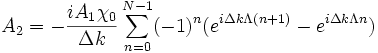
where  is the index of the poled domain. The total signal amplitude can be expressed as a sum
which integrates to
and reduces to
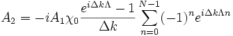
The summation yields

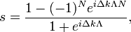
Multiply above equation both sides by a factor of 

Adding both equation leads to the relation

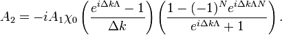
Solving for  gives
gives
which leads to
The total intensity can be expressed by

For the case of  the right part of the above equation is undefined so the limit needs to be taken when
  by invoking L'Hôpital's rule.
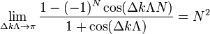
Which leads to the signal intensity
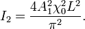
In order to allow different domain widths, i.e.  , for
, for 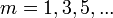 , the above equation becomes

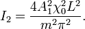
With  the intensity becomes
This allows quasi-phase-matching to exist at different domain widths  .
From this equation it is apparent, however, that as the quasi-phase match order
.
From this equation it is apparent, however, that as the quasi-phase match order  increases, the efficiency decreases by
  . For example for 3rd order quasi-phase matching only a third of the crystal is effectively used for the generation of signal frequency, as a consequence the amplitude of the signal wavelength only third of the amount of amplitude for same length crystal for 1st order quasi-phase match.
Calculation of domain width
The domain width is calculated through the use of Sellmeier equation and using wavevector relations. In the case of DFG this relationship holds true  where
where  are the pump, signal, and idler wavevectors and
  . By calculating for the different frequencies the domain width can be calculated from the relationship .
References
- ↑ Paschotta, Rüdiger. "Quasi-phase matching." Encyclopedia of Laser Physics and Technology. Retrieved April 30, 2006