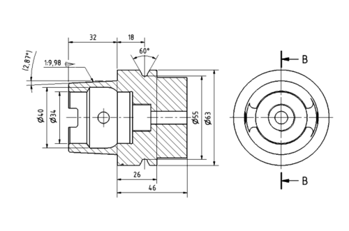
Production drawing
Production drawings[1][2][3] (sometimes called working drawings) are complete sets of drawings that detail the manufacturing and assembly of products. They are widely used as orthographic views of machine parts and their assembly. Production drawings are 'drawn (graphic) information, prepared by the design team for use by the construction or production team, the main purpose of which is to define the size, shape, location and production of the building or component'. For instance, if the engineering drawings call for a screw to be fastened to a specific torque, the production drawings would typically describe the tool used to fasten the screw and how it should be calibrated. The drawings may also outline the most convenient order in which to assemble components.[4]
Material and component specifics are provided in the title block of a production drawing. The sub-assembly or main assembly of a component, and where it will be assembled, are usually shown. Production drawings mention the number of parts that are required for making the assembled unit.
Engineering drawings are taken by production engineers who decide how best to manufacture the products. Machine operators, production line workers and supervisors all use production drawings. Design engineers also use orthographic or pictorial views to record their ideas, and these are called "working cases". These sketches are used for both the component and assembly drawings.
Drawing set
The three main sets of production drawings are:
- Detailing of each non-standard part on a drawing sheet, usually one part per sheet.
- Assembly drawing showing all parts on one sheet.
- A Bill of materials (BOM), essentially of each part.
Elements of production drawings
The basic elements of production drawings are:[5]
- Size and shape of component
- Format of drawing sheet
- Process sheet
- Projection method
- Limits, fits, and tolerances of size, form, and position
- Production method
- Indication of surface roughness and other heat treatments
- Material specification and Shape such as Castings, Forgings, Plates, Rounds, etc.
- Conventions used to represent certain machine compoents
- Inspection and Testing Methods
- Specification of Standard Components
Basic principles of dimensioning in production drawings
The basic principles of dimensioning in production drawings are:
- Each feature should be dimensioned only once on that drawing module
- No more dimensions than necessary should be shown on the drawing
- As far as possible, dimensions should be placed outside the drawing view
- Dimensions should be represented by visible outlines, rather than by hidden lines
- Dimensioning of the center line should be avoided except when it passes through the center hole
- Intersecting projection or dimension lines should be avoided
- If the space for dimensioning is insufficient, arrow heads may be reversed and adjacent arrow heads may be replaced by dots
Dimensioning technique
Any engineering drawing requires specifications in terms of dimensions.[6] Dimensions are classified as:
- Functional dimensions
- Non-functional dimensions
- Auxiliary dimensions
Non-functional dimensions dimensions are required for manufacturing.
Auxiliary dimensions do not govern manufacturing or inspection of parts. They are arranged in the following ways:
- Chain dimensioning: This method can be used only where the accumulation of tolerances does not affect the functional requirements.
- Parallel dimensioning: In this type of dimensioning, a number of single dimension lines are drawn parallel to one another, spaced so as to accommodate the dimensional values.
- Running dimensioning: This type of dimensioning is similar to parallel dimensioning; the only difference is that the dimensions are superimposed in one line. In this case the origin point should be marked.
- Coordinate dimensioning: The location of each hole and its size is given by specifying X and Y coordinates from the defined origin and tabulating them.
Production drawing in limits, fits and tolerance
Limit system
There are three terms used in the limit system:
- Tolerance: Deviation from a basic value is defined as Tolerance. It can be obtained by taking the difference between the maximum and minimum permissible limits.
- Limits: Two extreme permissible sizes between which the actual size is contained are defined as limits.
- Deviation: The algebraic difference between a size and its corresponding basic size. There are two types of deviations: 1) Upper deviation 2) Lower deviation
The fundamental deviation is either the upper or lower deviation, depending on which is closer to the basic size.
Tolerances
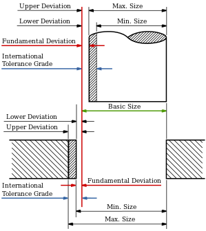
Due to human errors, machine settings, etc., it is nearly impossible to manufacture an absolute dimension as specified by the designer. Deviation in dimensions from the basic value always arises. This deviation of dimensions from the basic value is known as Tolerance.[6]
The figure shows mechanical tolerances which occur during operations.
Fits
The relation between two mating parts is called fit. Depending upon the actual limits of the hole or shaft sizes, fits may be classified as clearance fit, transition fit and interference fit.[8]
Clearance fit
Clearance fit is defined as a clearance between mating parts. In clearance fit, there is always a positive clearance between the hole and shaft.
Transition fit
Transition fit may result in either an interference or clearance, depending upon the actual values of the tolerance of individual parts.
Interference fit
Interference fit is obtained if the difference between the hole and shaft sizes is negative before assembly. Interference fit generally ranges from minimum to maximum interference. The two extreme cases of interference are as follows:
Minimum interference
The magnitude of the difference (negative) between the maximum size of the hole and the minimum size of the shaft in an interference fit before assembly.
Maximum interference
The magnitude of the difference between the minimum size of the hole and the maximum size of the shaft in an interference or a transition fit before assembly.
Hole Basis and shaft basis system: In identifying limit dimensions for the three classes of fit, two systems are in use:
- Hole basis system: The size of the shaft is obtained by subtracting the allowance from the basic size of the hole. Tolerances are then applied to each part separately. In this system, the lower deviation of the hole is zero. The letter symbol indication for this is 'H'.
- Shaft basis system: The upper deviation of the shaft is zero, and the size of the hole is obtained by adding the allowance to the basic size of the shaft. The letter symbol indication is 'h'.
Production drawing in surface roughness
The properties and performance of machine components are affected by the degree of roughness of various surfaces; the higher the smoothness of the surface, the greater the fatigue strength and corrosion resistance will be.[9] Friction between mating parts is also reduced by a smoother surface finish. The geometrical characteristics of the surface, in relation to roughness, are as follows:
- Macro-deviations
- Surface waviness
- Micro irregularities
Surface roughness can be evaluated with the height and mean roughness index of micro-irregularities. Surface roughness is defined by the following terms:
- Actual profile
- Reference profile
- Datum profile
- Main profile
- Mean roughness index
- Surface roughness number, etc.
Surface roughness number: The surface roughness number [R(a)] represents the average departure of the surface from the projections over the sampling length, which is expressed in micrometers. It is given by R(a)={h1+h2+h3+.....+hn}/n. Surface roughness can be measured using some of the following terms:
- Surface gauge
- Straight edge
- Profilograph
- Profilometer
- Optical flat, etc.
Production drawing and process sheets
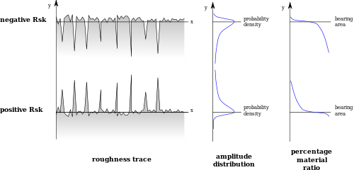
Production drawing roughness skew is shown in the accompanying figure.
Process sheets
The production drawing of a component is usually accompanied by a sheet known as a process sheet, which indicates the sequence of operations recommended for manufacturing. It should list the machinery, tooling and skills for each act or event. The process sheet should consist of the following:
- Description of the job
- Component number
- Size and weight
- Cycle time
- Drawing number
- Sequence number, etc.
Uses of process sheets
Process sheets provide:
- An overall view of the various operations that are to be performed for a job.
- Assistance with layout of the plant during the product design.
- Assistance in cost estimation, standard costs, production control and evaluation for productivity.
- Information for methods study personnel, to optimise the production process.
Principles of production drawings
Production drawings are to be prepared on standard size drawing sheets. The correct size of sheet and size of object can be visualized from the understanding of not the views of it but also from the various types of lines used, dimensions, notes, scales, etc. These drawings must be prepared to provide the correct information about the drawings to all the people concerned. In India standards are set by the Bureau of Indian Standards (BIS).
Drawing sheets
In production drawing standard size sheets are generally used to save paper and facilitate convenient storage of drawings. In specifications of sheets their size, the size of the title block and its position, the thickness of borders and frames etc., must be considered.
Sheet size
The basic principles to be followed in the sizes of drawing sheets are:
- X:Y=1:1.414
- X:Y=1, where X and Y are the sheet width and length.
For the reference size (A4), with a surface area of 1 sq meter, X=210mm and Y=297mm.
Title block
The title block, containing the identification of the drawing, should lie within the drawing space at the bottom right hand corner. The direction of viewing of the title block should correspond in general with that of the drawing. The block can have a maximum length of 170 mm.
See also
References
- ↑ K.L. Narayana. Production Drawing. New Age International. ISBN 81-224-0953-9.
- ↑ Bhatt, N.D. Machine Drawing. Charotar Publishing House. ISBN 978-81-85594-95-8.
- ↑ Reddy, Venkata (2009). Production Drawing. New Age International. ISBN 978-81-224-2288-7.
- ↑ Miller, John (1932). Production Drawings. Rice Institute.
- ↑ Narayana, K. Machine Drawing. ISBN 81-224-0953-9.
- ↑ 6.0 6.1 Machine Drawing & Computer Graphics, Farazdak Haideri, Nirali Prakashan. ISBN 978-93-8072-527-7
- ↑ Production Drawing, K.L. Narayana, New Age International Publishers. ISBN 81-224-0953-9
- ↑ Machine Drawing, P. Kannaiah, New Age International Publishers. ISBN 978-81-224-1917-7
- ↑ Pohit, Goutam (2002). Machine Drawing with AutoCAD. Pearson Education. ISBN 81-317-0677-X.