Pinhole camera
A pinhole camera is a simple camera without a lens and with a single small aperture, a pinhole – effectively a light-proof box with a small hole in one side. Light from a scene passes through this single point and projects an inverted image on the opposite side of the box. Exposures can typically range from five seconds up to as much as several hours. The effect was noted in the 5th century BC in China and has been refined over the centuries.
Description
A pinhole camera is completely dark on all the other sides of the box including the side where the point is created. This part is usually painted black, but black boxes are also used for this purpose. There is also a thin screen which looks like a projector sheet, and is put in between the dark side adjacent to the pinhole.
Up to a certain point, the smaller the hole, the sharper the image, but the dimmer the projected image. Optimally, the size of the aperture should be 1/100 or less of the distance between it and the projected image.
Because a pinhole camera requires a lengthy exposure, its shutter may be manually operated, as with a flap made of light-proof material to cover and uncover the pinhole. Typical exposures range from five seconds to several hours.
A common use of the pinhole camera is to capture the movement of the sun over a long period of time. This type of photography is called solargraphy.
The image may be projected onto a translucent screen for real-time viewing (popular for observing solar eclipses; see also camera obscura), or can expose photographic film or a charge coupled device (CCD). Pinhole cameras with CCDs are often used for surveillance because they are difficult to detect.
Pinhole devices provide safety for the eyes when viewing solar eclipses because the event is observed indirectly, the diminished intensity of the pinhole image being harmless compared with the full glare of the Sun itself.
World Pinhole Day is held on the last Sunday of April.[1]
Invention
The camera obscura was not so much an invention as a discovery and development. The camera obscura works on a naturally occurring phenomenon (the rectilinear propagation of light) and can, for example, often be observed when sunlight filters through dense leaves. Over the centuries many people made contributions to the design of camera obscura as we know it but all are based on the underlying optical laws that apply in nature.[2]
In the 5th century BC, the Mohist philosopher Mozi (墨子) in ancient China mentioned the effect of an inverted image forming through a pinhole.[3] The image of an inverted Chinese pagoda is mentioned in Duan Chengshi's (d. 863) book Miscellaneous Morsels from Youyang written during the Tang Dynasty (618–907).[4] Along with experimenting with the pinhole camera and the burning mirror of the ancient Mohists, the Song Dynasty (960–1279 CE) Chinese scientist Shen Kuo (1031–1095) experimented with the camera obscura and was the first to establish geometrical and quantitative attributes for it.[4]
The Greek philosopher Aristotle observed the phenomenon in the fourth century BC. In his book Problems, he wrote:
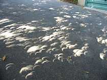
"Why is it that when the sun passes through quadri-laterals, as for instance in wickerwork, it does not produce a figure rectangular in shape but circular?” and further "Why is it that an eclipse of the sun, if one looks at it through a sieve or through leaves, such as a plane-tree or other broadleaved tree, or if one joins the fingers of one hand over the fingers of the other, the rays are crescent-shaped where they reach the earth? Is it for the same reason as that when light shines through a rectangular peep-hole, it appears circular in the form of a cone?”
A description was given early in the eleventh century Alhazen in his work The Shape of the Eclipse[5]
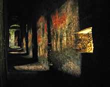
This treatise is of special interest because of what it reveals about Ibn al-Haytham’s knowledge of the important subject of the camera obscura. The exact Arabic equivalent of that Latin phrase, al-bayt al-muzlim, occurs in book I, chapter 3 of the Optics;19 and indeed dark chambers are frequently used in this book for the study of such various properties of light as its rectilinear propagation and the fact that shining bodies radiate their light and color on neighboring objects. But such images as those produced by a pinhole camera are totally absent from the Optics. The nearest that Ibn al-Haytham gets to such an image is the passage in which he describes the patches of light cast on the inside wall of a “dark place” by candle flames set up at various points opposite a small aperture that leads into the dark place; the order of the images on the inside wall is the reverse of the order of the candles outside.
The experiment was designed to show that the light from one candle is not mingled with the light from another as a result of their meeting at the aperture, and in general that lights and colors are not affected by crossing one another. Although this passage occurs in book I in the context of the theory of vision,20 the eye does not in Ibn al-Haytham’s explanation act as a pinhole camera and it is expressly denied the role of a lens camera. In the present treatise, however, he approached the question, already posed in the pseudo-Aristotelian Problemata, of why the image of a crescent moon, cast through a small circular aperture, appears circular, whereas the same aperture will cast a crescent-shaped image of the partially eclipsed sun. Although his answer is not wholly satisfactory, and although he failed to solve the general problem of the pinhole camera, his attempted explanation of the image of a solar crescent clearly shows that he possessed the principles of the working of the camera. He formulated the condition for obtaining a distinct image of an object through a circular aperture as that when: where ma, ms are the diameters of the aperture and of the object respectively, and da, ds the distances of the screen from the aperture and from the object respectively.
.
In the 13th century, Robert Grosseteste and Roger Bacon commented on the pinhole camera.[6] Between 1000 and 1600, men such as Ibn al-Haytham, Gemma Frisius, and Giambattista della Porta wrote on the pinhole camera, explaining why the images are upside down.
Around 1600, Giambattista della Porta added a lens to the pinhole camera.[7][8] It was not until 1850 that a Scottish scientist by the name of Sir David Brewster actually took the first photograph with a pinhole camera. Up until recently it was believed that Brewster himself coined the term "Pinhole" in "The Stereoscope". The earliest reference to the term "Pinhole" has been traced back to almost a century before Brewster to James Ferguson's Lectures on select Subjects.[9][10] Sir William Crookes and William de Wiveleslie Abney were other early photographers to try the pinhole technique.[11]

Selection of pinhole size
Within limits, a smaller pinhole (with a thinner surface that the hole goes through) will result in sharper image resolution because the projected circle of confusion at the image plane is practically the same size as the pinhole. An extremely small hole, however, can produce significant diffraction effects and a less clear image due to the wave properties of light.[12] Additionally, vignetting occurs as the diameter of the hole approaches the thickness of the material in which it is punched, because the sides of the hole obstruct the light entering at anything other than 90 degrees.
The best pinhole is perfectly round (since irregularities cause higher-order diffraction effects), and in an extremely thin piece of material. Industrially produced pinholes benefit from laser etching, but a hobbyist can still produce pinholes of sufficiently high quality for photographic work.
One method is to start with a sheet of brass shim or metal reclaimed from an aluminium drinks can or tin foil/aluminum foil, use fine sand paper to reduce the thickness of the centre of the material to the minimum, before carefully creating a pinhole with a suitably sized needle.
A method of calculating the optimal pinhole diameter was first attempted by Jozef Petzval. The crispest image is obtained using a pinhole size determined by the formula[13]

where d is pinhole diameter, f is focal length (distance from pinhole to image plane) and λ is the wavelength of light.
For standard black-and-white film, a wavelength of light corresponding to yellow-green (550 nm) should yield optimum results. For a pinhole-to-film distance of 1 inch (25 mm), this works out to a pinhole 0.17 mm in diameter.[14] For 5 cm, the appropriate diameter is 0.23 mm.[15]
The depth of field is basically infinite, but this does not mean that no optical blurring occurs. The infinite depth of field means that image blur depends not on object distance, but on other factors, such as the distance from the aperture to the film plane, the aperture size, and the wavelength(s) of the light source.

In the 1970s, Young measured the resolution limit of the pinhole camera as a function of pinhole diameter[16] and later published a tutorial in The Physics Teacher.[17] Partly to enable a variety of diameters and focal lengths, he defined two normalized variables: pinhole radius divided by resolution limit, and focal length divided by the quantity s2/λ, where s is the radius of the pinhole and λ is the wavelength of the light, typically about 550 nm. His results are plotted in the figure.
To the left, the pinhole is large, and geometric optics applies; the resolution limit is about 1.5 times the radius of the pinhole. (Spurious resolution is also seen in the geometric-optics limit.) To the right, the pinhole is small, and Fraunhofer diffraction applies; the resolution limit is given by the far-field diffraction formula shown in the graph and now increases as the pinhole is made smaller. In the region of near-field diffraction (or Fresnel diffraction), the pinhole focuses the light slightly, and the resolution limit is minimized when the focal length f (the distance between the pinhole and the film plane) is given by f = s2/λ. At this focal length, the pinhole focuses the light slightly, and the resolution limit is about 2/3 of the radius of the pinhole. The pinhole in this case is equivalent to a Fresnel zone plate with a single zone. The value s2/λ is in a sense the natural focal length of the pinhole.
The relation f = s2/λ yields an optimum pinhole diameter d = 2 √(fλ), so the experimental value differs slightly from the estimate of Petzval, above.
Construction
Pinhole cameras can be handmade by the photographer for a particular purpose. In its simplest form, the photographic pinhole camera can consist of a light-tight box with a pinhole in one end, and a piece of film or photographic paper wedged or taped into the other end. A flap of cardboard with a tape hinge can be used as a shutter. The pinhole may be punched or drilled using a sewing needle or small diameter bit through a piece of tinfoil or thin aluminum or brass sheet. This piece is then taped to the inside of the light-tight box behind a hole cut through the box. A cylindrical oatmeal container may be made into a pinhole camera.
Pinhole cameras can be constructed with a sliding film holder or back so the distance between the film and the pinhole can be adjusted. This allows the angle of view of the camera to be changed and also the effective f-stop ratio of the camera. Moving the film closer to the pinhole will result in a wide angle field of view and a shorter exposure time. Moving the film farther away from the pinhole will result in a telephoto or narrow angle view and a longer exposure time.
Pinhole cameras can also be constructed by replacing the lens assembly in a conventional camera with a pinhole. In particular, compact 35 mm cameras whose lens and focusing assembly have been damaged can be reused as pinhole cameras—maintaining the use of the shutter and film winding mechanisms. As a result of the enormous increase in f-number while maintaining the same exposure time, one must use a fast film in direct sunshine.
Pinholes (homemade or commercial) can be used in place of the lens on an SLR. Use with a digital SLR allows metering and composition by trial and error, and is effectively free, so is a popular way to try pinhole photography.[18]
Unusual materials have been used to construct pinhole cameras, e.g., a Chinese roast duck.[19] by Martin Cheung
Calculating the f-number & required exposure

The f-number of the camera may be calculated by dividing the distance from the pinhole to the imaging plane (the focal length) by the diameter of the pinhole. For example, a camera with a 0.5 mm diameter pinhole, and a 50 mm focal length would have an f-number of 50/0.5, or 100 (f/100 in conventional notation).
Due to the large f-number of a pinhole camera, exposures will often encounter reciprocity failure.[20] Once exposure time has exceeded about 1 second for film or 30 seconds for paper, one must compensate for the breakdown in linear response of the film/paper to intensity of illumination by using longer exposures.
Other special features can be built into pinhole cameras such as the ability to take double images, by using multiple pinholes, or the ability to take pictures in cylindrical or spherical perspective by curving the film plane.
These characteristics could be used for creative purposes. Once considered as an obsolete technique from the early days of photography, pinhole photography is from time to time a trend in artistic photography.
Related cameras, image forming devices, or developments from it include Franke's widefield pinhole camera, the pinspeck camera, and the pinhead mirror.
NASA (via the NASA Institute for Advanced Concepts) has funded initial research into the New Worlds Mission project, which proposes to use a pinhole camera with a diameter of 10 m and focus length of 200,000 km to image earth sized planets in other star systems.
Coded apertures
A non-focusing coded-aperture optical system may be thought of as multiple pinhole cameras in conjunction. By adding pinholes, light throughout and thus sensitivity are increased. However, multiple images are formed, usually requiring computer deconvolution.
See also
| Alternative photography |
|---|
 |
- Pinhole glasses
- Spatial filter
- Zone plate
- Dirkon
- Ibn al-Haytham
- Fox Talbot
- Wolf Howard
- Billy Childish
- Jesse Richards
- Pinhole camera model
- Nautilus (its pinhole eye functions as a camera)
- Pinhole occluder, a similar device used by ophthalmologists
- Camera obscura, uses the same principle as a pinhole camera
- The Great Picture
References
- ↑ http://www.bbc.co.uk/news/in-pictures-22150973
- ↑ Frequently asked questions about camera obscuras
- ↑ Needham, Joseph (1986). Science and Civilization in China: Volume 4, Physics and Physical Technology, Part 1, Physics. Taipei: Caves Books Ltd. Page 82.
- ↑ 4.0 4.1 Needham, Joseph (1986). Science and Civilization in China: Volume 4, Physics and Physical Technology, Part 1, Physics. Taipei: Caves Books Ltd. Page 98.
- ↑ ["Ibn Al-Haytham, Abū http://www.encyclopedia.com/doc/1G2-2830901904.html "Ibn Al-Haytham, Abū http://www.encyclopedia.com/doc/1G2-2830901904.html]. Retrieved 6 January 2015. Missing or empty
|title=(help) - ↑ A reconsideration of Roger Bacon's theory of pinhole images
- ↑ History of Photography and the Camera – Pinhole Camera to Daguerreotype
- ↑ http://www-history.mcs.st-andrews.ac.uk/Biographies/Porta.html
- ↑ James Ferguson. Lectures on select subjects in mechanics, hydrostatics, pneumatics, and optics with the...
- ↑ What is a Pinhole Camera?
- ↑ Pinhole photography history
- ↑ Hecht, Eugene (1998). "5.7.6 The Camera". Optics (3rd ed.). ISBN 0-201-30425-2.
- ↑ Rayleigh, (1891) Lord Rayleigh on Pin-hole Photography in Philosophical Magazine, vol.31, pp. 87–99 presents his formal analysis, but the layman's formula "pinhole radius = √(ƒλ)" appears in Strutt,J.W. Lord Rayleigh (1891) Some applications of photography in Nature. Vol.44 p.254.
- ↑ Equation for calculation with f=1in, using Google for evaluation
- ↑ Equation for calculation with f=5cm, using Google for evaluation
- ↑ M. Young, "Pinhole optics," Applied Optics 10, 2763-2767 (1971); <http://www.opticsinfobase.org/ao/abstract.cfm?URI=ao-10-12-2763>.
- ↑ Matt Young, “The pinhole camera: Imaging without lenses or mirrors,” The Physics Teacher 27, 648-655 (1989); <http://dx.doi.org/10.1119/1.2342908>.
- ↑ http://www.pcw.co.uk/personal-computer-world/features/2213298/hands-digital-pinhole-camera
- ↑ http://www.urbanphoto.net/blog/2010/11/25/how-a-roast-duck-sees-chinatown/
- ↑ http://www.nancybreslin.com/pinholetech.html
External links
| Wikimedia Commons has media related to Pinhole photography. |
- pinhole.cz
- Pinhole Photography by Vladimir Zivkovic
- Worldwide Pinhole Photography Day website
- An easy way to convert a DSLR to a pinhole camera
- Pinhole Photography and Camera Design Calculators
- Illustrated history of cinematography
- How to Make and Use a Pinhole Camera
- Oregon Art Beat: Pinhole Photos by Zeb Andrews
Further reading
- Eric Renner Pinhole Photography: From Historic Technique to Digital Application