Pentode
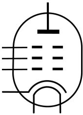
Electrodes from top to bottom:
:anode (plate)
:suppressor grid
:screen grid
:control grid
:cathode
:heater (filament)
A pentode is an electronic device having five active electrodes. The term most commonly applies to a three-grid amplifying vacuum tube (thermionic valve), which was invented by Gilles Holst and Bernhard D.H. Tellegen in 1926.[1] The pentode consists of an evacuated glass envelope containing five electrodes in this order: a cathode heated by a filament, a control grid, a screen grid, a suppressor grid, and a plate (anode). The pentode (called a "triple-grid amplifier" in some early literature[2]) was developed from the tetrode tube by the addition of a third grid, the suppressor grid. This served to prevent secondary emission electrons emitted by the plate from reaching the screen grid, which caused instability and parasitic oscillations in the tetrode. The pentode is closely related to the beam tetrode. Pentodes were widely used in industrial and consumer electronic equipment such as radios and televisions until the 1960s, when they were replaced by transistors. Their main use now is in high power industrial applications such as radio transmitters. The obsolete consumer tubes are still used in a few legacy and specialty vacuum tube audio devices.
Types of pentodes
- Variable transconductance ("variable-mu", "remote-cutoff" or "super-control") tubes in general are those with a non-uniform grid wire spacing to allow them to handle a wide range of input signal levels without excessive cross-modulation distortion, and so useful in radio frequency stages where automatic gain control is applied to the pentode. The first commercial variable-mu tubes were the 550 and 551 developed by Stuart and Snow around 1929.[3] Other examples include: EF50, 1T4, 6K7, 6BA6, and the EF83 (while perhaps the EF85/6BY7, and certainly the 6JH6, could be described as "semiremote-cutoff" pentodes).
- Sharp-cutoff ("high slope" or ordinary) pentodes have the more ordinary uniform spacing of grid wires, and so mutual conductance decreases in an essentially uniform manner with increasing negative bias, and has a more abrupt cutoff. These pentodes are more suitable for audio amplifiers. Examples include: EF37A, EF86/6267, 1N5GT, 6AU6A, 6J7GT. Often, but not always, in the European valve naming scheme for pentodes an even number indicated a sharp-cutoff device while odd indicated remote-cutoff; the EF37 was an exception to this general trend, perhaps due to its history as an update to the EF36 ("The Mullard EF36, EF37 and EF37A" at the National Valve Museum).
- Power output pentodes, The EL34, EL84, 6CL6, 6F6, 6G6, SY4307A and 6K6GT are some examples of true pentodes used for power amplification, using a suppressor grid rather than the higher efficiency beam-forming plates used in beam tetrodes. (Beam tetrodes were also sometimes referred to as "beam pentodes",[4] and include the Sylvania (and possibly GE) 6CA7 version of EL34, 6V6GT and the GEC KT66 and KT88. Other sources perferred names such as "beam power amplifier" or "beam power tube", possibly due to caution regarding the Philips pentode patent). Power output pentodes for specific television requirements, efficient for their job but possibly not linear enough for audio, were named:
- video output pentodes, e.g. 15A6/PL83, PL802
- frame output or vertical deflection pentodes, such as the PL84 and the pentode sections of the 18GV8/PCL85.
- line output or horizontal deflection pentodes, such as the PL36, 27GB5/PL500, PL505 etc.
- A "triode-pentode" is a single envelope containing both a triode and a pentode, such as an ECF80 or ECL86.
Advantages over the tetrode
The simple tetrode tube -also called a 'straight tetrode'- offered a larger amplification factor, more power and a higher frequency capability than the earlier triode. However, in the tetrode the anode may emit more secondary electrons than it receives (the excess being collected by the nearby screen grid). Secondary electrons are those knocked out of the anode when the electrons from the cathode strike it. The result is a reversal of net anode current. In other words, the anode current Ia is found to decrease with increasing anode voltage Va, over part of the characteristic curve. This negative anode resistance (ΔVa/ΔIa < 0) can cause the tetrode to become unstable, leading to oscillation in some circumstances.
The pentode, as introduced by Tellegen, has an additional electrode, or third grid, called the suppressor grid, located between the screen grid and the anode, which solves the problem of secondary emission. The suppressor grid is given a low potential, it is usually either grounded or connected to the cathode. Secondary emission electrons from the anode are repelled by the negative potential on the suppressor grid, so they can't reach the screen grid but return to the anode. The primary electrons from the cathode have a higher kinetic energy, so they can still pass through the suppressor grid and reach the anode.
Pentodes, therefore, can have higher current outputs and a wider output voltage swing; the anode/plate can even be at a lower voltage than the screen grid yet still amplify well.[5]
Comparisons with the triode
- Pentodes (and tetrodes) tend to have a much lower feedback capacitance, due to the screening effect of the second grid.
- Pentodes tend to have a higher noise (partition noise),
- Triodes have a lower internal anode resistance, and hence higher damping factor when used in audio output circuits, compared with pentodes, when negative feedback is absent. That also reduces the potential voltage amplification obtainable from a triode compared with a pentode of the same transconductance, and usually means a more efficient output stage can be made using pentodes, with a lower power drive signal.
- Pentodes are almost unaffected by changes in supply voltage, and can thus operate with more poorly stabilized supplies than triodes. An examination of the characteristics shown here will show that the plate current hardly changes as plate voltage varies.
- Pentodes and triodes (and tetrodes) do have essentially similar relationships between grid (one) input voltage and anode output current when the anode voltage is held constant, i.e. close to a square-law relationship.
Usage

Pentode tubes were first used in consumer-type radio receivers. A well-known pentode type, the EF50, was designed before the start of World War II, and was extensively used in radar sets and other military electronic equipment. The pentode contributed to the electronic preponderance of the Allies.
The Colossus computer and the Manchester Small-Scale Experimental Machine used huge numbers of EF36 pentode tubes.[6][7][8][9]
After World War II, pentodes were widely used in TV receivers, particularly the successor to the EF50, the EF80. Vacuum tubes were replaced by transistors during the 1960s. However, they continue to be used in certain applications, including high-power radio transmitters and (because of their well-known valve sound) in high-end and professional audio applications, microphone preamplifiers and electric guitar amplifiers. Large stockpiles in countries of the former Soviet Union have provided a continuing supply of such devices, some designed for other purposes but adapted to audio use, such as the GU-50 transmitter tube.
Triode-strapped pentode circuits
A pentode can have its screen grid (grid 2) connected to the anode (plate), in which case it reverts to an ordinary triode with commensurate characteristics (lower anode resistance, lower mu, lower noise, more drive voltage required). The device is then said to be "triode-strapped" or "triode-connected". This is sometimes provided as an option in audiophile pentode amplifier circuits, to give the sought-after "sonic qualities" of a triode power amplifier. A resistor may be included in series with the screen grid to avoid exceeding the screen grid's power or voltage rating, and to prevent local oscillation. Triode-connection is a useful option for audiophiles who wish to avoid the expense of 'true' power triodes.
See also
- Beam tetrode
- Pentode transistor
- Valve audio amplifier – technical
- List of vacuum tubes
- Tube Data Archive, thousands of tube data sheets
References
- ↑ G. Holst and B.D.H. Tellegen, "Means for amplifying electrical oscillations", US Patent 1945040, January 1934.
- ↑ "RCA Receiving Tube Manual, 1940"; p118
- ↑ Stuart, B & Snow, H. A. (1930). Reduction of Distortion and Cross-Talk in Radio Receivers by Mean of Variable-Mu Tetrodes. Proc IRE, Vol 18, Issue 12, pp2102 - 2127
- ↑ "Sylvania Receiving Tubes Technical Manual, 14th Edition" p 143
- ↑ "RCA Receiving Tube Manual, 1940"; p8.
- ↑ Tony Sale. "The Colossus Rebuild Project"
- ↑ Tony Sale. "The Colossus: its purpose and operation".
- ↑ Michael Saunby. "Small signal audio pentodes".
- ↑ B. Jack Copeland. "Colossus: The secrets of Bletchley Park's code-breaking computers".
| Wikimedia Commons has media related to pentodes. |
| ||||||||||||||||||||||||||||||||||
| ||||||||||||||||||