Newton 6-inch Mortar
| Newton 6 inch Mortar | |
|---|---|
|
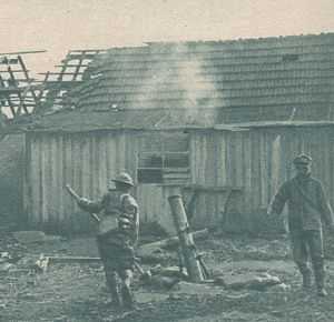
Canadian troops firing the 6-inch (152.4 mm) Mortar in the open at Valenciennes in 1918 | |
| Type | Medium mortar |
| Place of origin | United Kingdom |
| Service history | |
| In service | 1917 - 1918 |
| Used by |
British Empire United States |
| Wars | World War I |
| Production history | |
| Designer | Captain H Newton, 5th Btn Sherwood Foresters |
| Designed | 1916 |
| Number built | UK : 2,538[1] |
| Specifications | |
| Barrel length |
Bore: 4 ft 6 in (1.37 m) Total: 4 ft 9 in (1.45 m)[2] |
|
| |
| Shell | HE 52 lb (24 kg)[3] |
| Calibre | 6 inches (152.4 mm) |
| Elevation | 77°–45° |
| Rate of fire | 8 rounds/min[4] |
| Effective firing range |
100 - 1,420 yds (91 - 1,298 m) |
| Maximum firing range | 1,950 yd (1,780 m)[5] |
| Filling | Amatol, Ammonal or Sabulite |
| Filling weight | 22 pounds (9.98 kg) |
The Newton 6 inch Mortar was the standard British medium mortar in World War I from early 1917 onwards.
Description
The Newton 6 inch replaced the 2 inch Medium Mortar beginning in February 1917.
It was a simple smooth bore muzzle-loading (SBML) mortar consisting of a 57-inch (1,448 mm) one-piece steel tube barrel, with a "striker stud" inside the centre of the closed base of the tube. The rounded external base of the tube sat in a socket in the flat cast steel base, which in turn sat on a wooden platform. An "elevating guy" (cable) connected to a loop in the upper side of the barrel and the rear end of the bed. "Traversing guys" (cables) connected to loops on each side of the barrel and eyebolts on the upper sides of the bed. Hence aiming of the barrel was done by adjusting the length of the guys via adjusting screws. A socket in the barrel base allowed for emergency firing via a "misfire plug" in the case of misfires (i.e. if the bomb remained in the barrel due to failure of the propellant to ignite).[6]
Combat service

British Empire Divisions were initially equipped with 3 batteries of 4 mortars designated X, Y, Z. From February 1918 onwards these were consolidated into 2 batteries, X and Y, of 6 mortars each, and Z was dissolved. In British use they were operated by the Royal Field Artillery and formed part of the Divisional Artillery with 1 battery attached to each of the Divisional artillery brigades.
The United States Army began production and equipping with this mortar late in the war but it is doubtful whether any were used in combat.

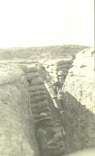
The mortar was operated from concealed pits close to the front line during trench warfare, and was used in the open during the final "mobile warfare" phase of the First World War, as demonstrated in the photograph, depending on available transport. The disassembled weapon was usually transported on horsedrawn carts but the Canadian Automobile Machine Gun Brigade (the Canadian Independent Force or "Brutinel's Brigade") is known to have successfully used the mortar both mounted on motor trucks and dismounted in the closing months of the war.[7][8]
The 52-pound cast-iron fin-stabilised high explosive bomb carried the percussion primer at the base in the intersection of the 4 vanes (fins), consisting of a specially loaded blank .303 rifle cartridge. The basic propellant charges were contained in 4 small white cambric bags each containing 1 oz of guncotton yarn. These were held in place in the 4 angles between the bomb's fins. For ranges less than 1000 yards 1 or more bags could be removed, as per range tables.
For ranges above 1,000 yards (910 m), additional charges were loaded before the bomb, held in 2 white cambric bags each containing 1 oz 4 drm cordite.[9]
In action the gunners would adjust the angle of the barrel via the elevating guy (for distance) and traversing guys (for direction). The manual warns: "See that the elevating and traversing screws of the guys are always tight. A slack guy leads to inaccurate shooting, and the stresses on firing are not equally distributed; this is usually the cause of the guys breaking".[10]
The range tables specified the barrel angle and propellant charges required. The additional cordite propelling charge bags were dropped down the barrel if necessary, or necessary number of propellant charges removed from the bomb, and the bomb's fuze was set. The gunners stood back, the bomb was dropped down the barrel, the detonator in the base of the .303 cartridge in the base of the bomb struck a pin in the bottom of the barrel and fired, igniting the guncotton charges in the base of the bomb, which in turn ignited the cordite charges if present. The resulting rapid gas expansion propelled the bomb up the barrel and to its target.
1917 Range tables
52 lb Bomb, ML 6 inch Trench Mortar.
Propellant : 1-4 one ounce guncotton charges in the base of the bomb, plus optional 2.5 oz cordite charge.[11]
| Range (yards) |
1 oz charge degrees |
2 oz charge degrees |
3 oz charge degrees |
4 oz charge degrees |
4 oz + 2.5 oz cordite | |
|---|---|---|---|---|---|---|
| degrees | seconds | |||||
| 100 | 77 | |||||
| 120 | 74 | |||||
| 140 | 71 | |||||
| 160 | 67.5 | |||||
| 180 | 63.5 | |||||
| 200 | 59 | |||||
| 220 | 47.5 | 77.25 | ||||
| 226 | 45 | |||||
| 240 | 76 | |||||
| 260 | 74.75 | |||||
| 280 | 73.25 | |||||
| 300 | 72 | |||||
| 320 | 70.5 | 77.5 | ||||
| 340 | 69 | 76.75 | ||||
| 360 | 67.5 | 76 | ||||
| 380 | 66 | 75 | ||||
| 400 | 64.25 | 74.25 | ||||
| 420 | 62.25 | 73.25 | ||||
| 440 | 60.25 | 72.25 | 77.25 | |||
| 460 | 57.75 | 71.5 | 76.5 | |||
| 480 | 55 | 70.5 | 76 | |||
| 500 | 50.5 | 69.5 | 75.25 | |||
| 510 | 45 | |||||
| 520 | 68.5 | 74.5 | ||||
| 540 | 67.5 | 74 | ||||
| 560 | 66.25 | 73.25 | ||||
| 580 | 65.25 | 72.5 | ||||
| 600 | 64 | 72 | ||||
| 620 | 62.75 | 71.25 | ||||
| 640 | 61.25 | 70.5 | ||||
| 660 | 59.75 | 69.75 | ||||
| 680 | 58.25 | 69 | ||||
| 700 | 56.5 | 68.25 | 75.25 | 23.9 | ||
| 720 | 54.5 | 67.5 | 74.75 | 23.9 | ||
| 740 | 51.75 | 66.75 | 74.25 | 23.8 | ||
| 760 | 45.5 | 65.75 | 73.75 | 23.8 | ||
| 761 | 45 | |||||
| 780 | 65 | 73.25 | 23.7 | |||
| 800 | 64 | 72.75 | 23.6 | |||
| 820 | 63.25 | 72.25 | 23.6 | |||
| 840 | 62.25 | 71.75 | 23.5 | |||
| 860 | 61 | 71.25 | 23.4 | |||
| 880 | 60 | 70.75 | 23.4 | |||
| 900 | 58.75 | 70.25 | 23.3 | |||
| 920 | 57.5 | 69.75 | 23.2 | |||
| 940 | 56 | 69.25 | 23.1 | |||
| 960 | 54.5 | 68.75 | 23.1 | |||
| 980 | 52.5 | 68.25 | 23.0 | |||
| 1000 | 50 | 67.5 | 22.9 | |||
| 1016 | 45 | |||||
| 1020 | 67 | 22.8 | ||||
| 1040 | 66.5 | 22.7 | ||||
| 1060 | 66 | 22.6 | ||||
| 1080 | 65.25 | 22.5 | ||||
| 1100 | 64.5 | 22.8 | ||||
| 1120 | 64 | 22.2 | ||||
| 1140 | 63.25 | 22.1 | ||||
| 1160 | 62.75 | 22.0 | ||||
| 1180 | 62 | 21.8 | ||||
| 1200 | 61.25 | 21.7 | ||||
| 1220 | 60.5 | 21.5 | ||||
| 1240 | 59.5 | 21.3 | ||||
| 1260 | 58.75 | 21.1 | ||||
| 1280 | 57.75 | 20.9 | ||||
| 1300 | 56.75 | 20.7 | ||||
| 1320 | 55.75 | 20.4 | ||||
| 1340 | 54.75 | 20.2 | ||||
| 1360 | 53.5 | 19.9 | ||||
| 1380 | 52 | 19.5 | ||||
| 1400 | 50 | 19.0 | ||||
| 1420 | 45 | 17.5 | ||||
Image gallery
-

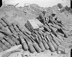
Men of the 9th Btn Royal Sussex Regt and mortar bomb dump near Lens, September 3, 1918 -

Mk III bomb diagram -

Bomb at Hawthorn Crater, Somme 1998. Photograph by Marco Hoveling http://www.unfortunate-region.org
See also
Weapons of comparable role, performance and era
- Mortier de 58 mm type 2 : approximate French equivalent
Surviving examples
- Army Memorial Museum, Waiouru, New Zealand
- Royal Australian Artillery Museum, North Head, Sydney, Australia
- Australian Army Infantry Museum, Singleton NSW Australia
Notes and references
- ↑ Ministry of Munitions 1922, pages 130-131
- ↑ Preliminary Notes on the M.L. 6-Inch Trench Mortar Mark I. 1917
- ↑ 52 lb total weight for bomb is quoted in Range Tables. Preliminary Notes on the M L 6-inch Trench Mortar, Mark I. Handbook of the M L 6-inch Trench Mortar Mark I.
- ↑ Ministry of Munitions 1922, page 66
- ↑ A maximum range of 1,950 yards was eventually achieved after improvements. Ministry of Munitions 1922, page 66
- ↑ Preliminary Notes on the M.L. 6-Inch Trench Mortar, Mark I, 1917, page 1
- ↑ Michael Holden, University of New Brunswick, "Training, Multi-National Formations, and Tactical Efficiency: The Canadian Motor Machine Gun Brigades in 1918"
- ↑ Danish Military History Society, "The Canadian Motor Machine Gun Brigade, Part 1"
- ↑ Handbook of the M.L. 6-Inch Trench Mortar Mark I. 1918
- ↑ Handbook of the M.L. 6-Inch Trench Mortar Mark I. 1918, page 10
- ↑ Preliminary Notes, 1917
Bibliography
- Preliminary Notes on the M.L. 6-Inch Trench Mortar Mark I. 1917. War Office, UK.
- Handbook of the M.L. 6-Inch Trench Mortar Mark I. 1918. War Office, UK.
- W L Ruffell, "An example of Kiwi ingenuity. A carriage designed by the Divisional Trench Mortars to meet the changed conditions of fighting in the last advances of 1918"
- Handbook of artillery : including mobile, anti-aircraft and trench matériel (1920). United States. Army. Ordnance Dept, May 1920
- "History of the Ministry of Munitions", 1922. Volume XI, Part I Trench Warfare Supplies. Facsimile reprint by Imperial War Museum and Naval & Military Press, 2008 ISBN 1-84734-885-8
External links
| Wikimedia Commons has media related to Newton 6 inch Mortar. |
- Imperial War Museum Collection Search Weaponry Inventions and Improvements by Captain H Newton during the First World War a manuscript detailing Captain Newton's work on this and other weapons, written by his nephew and held by the Imperial War Museum.
- "Provisional drill regulations for trench mortar batteries; 6" Newton and the 240 mm. : chapters II, VI, and VIII". United States. War Dept, 1918. Made available online by Combined Arms Research Library
- "Handbook on trench mortar fuzes, Mark VII and Mark VII-E.". United States. War Dept, 1918. Made available online by Combined Arms Research Library
- "Manual for trench artillery, United States Army (provisional). Part I, trench artillery.". United States. War Dept, July 1918. Made available online by Combined Arms Research Library
- "Manual for trench artillery, United States Army (provisional). Part II, formations and maneuvers". United States. War Dept, 1918. Made available online by Combined Arms Research Library
- WL Ruffell, The 6-inch Mortar from "The Mortar"
- 6-inch Newton Mortar at Landships
| ||||||||||||||||||||||||||||||||||||||||||||||||||||||||||||||||||||
