Negative impedance converter
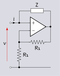
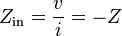
The negative impedance converter (NIC) is a one-port op-amp circuit acting as a negative load which injects energy into circuits in contrast to an ordinary load that consumes energy from them. This is achieved by adding or subtracting excessive varying voltage in series to the voltage drop across an equivalent positive impedance. This reverses the voltage polarity or the current direction of the port and introduces a phase shift of 180° (inversion) between the voltage and the current for any signal generator. The two versions obtained are accordingly a negative impedance converter with voltage inversion (VNIC) and a negative impedance converter with current inversion (INIC). The basic circuit of an INIC and its analysis is shown below.
Basic circuit and analysis

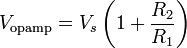
INIC is a non-inverting amplifier (the op-amp and the voltage divider R1, R2 on the figure) with a resistor (R3) connected between its output and input. The op-amp output voltage is
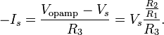
The current going from the operational amplifier output through resistor  toward the source
  is
is  , and
, and
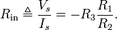
So the input experiences an opposing current that is proportional to , and the circuit acts like a resistor with negative resistance
In general, elements  ,
,  , and need not be pure resistances (i.e., they may be capacitors, inductors, or impedance networks).
Application
By using an NIC as a negative resistor, it is possible to let a real generator behave (almost) like an ideal generator, (i.e., the magnitude of the current or of the voltage generated does not depend on the load).
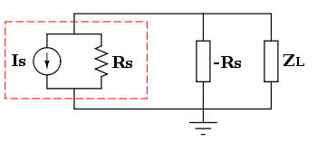
An example for a current source is shown in the figure on the right. The current generator and the resistor within the dotted line is the Norton representation of a circuit comprising a real generator and  is its internal resistance. If an INIC is placed in parallel to that internal resistance, and the INIC has the same magnitude but inverted resistance value, there will be and
  in parallel. Hence, the equivalent resistance is

That is, the combination of the real generator and the INIC will now behave like a composed ideal current source; its output current will be the same for any load  . In particular, any current that is shunted away from the load into the Norton equivalent resistance will be supplied by the INIC instead.
The ideal behavior in this application depends upon the Norton resistance and the INIC resistance  being matched perfectly. As long as
  , the equivalent resistance of the combination will be greater than ; however, if
  , then the impact of the INIC will be negligible. However, when

the circuit is unstable (e.g., when  in an unloaded system). In particular, the surplus current from the INIC generates positive feedback that causes the voltage driving the load to reach its power supply limits. By reducing the impedance of the load (i.e., by causing the load to draw more current), the generator–NIC system can be rendered stable again.
In principle, if the Norton equivalent current source was replaced with a Norton equivalent voltage source, a VNIC of equivalent magnitude could be placed in series with the voltage source's series resistance. Any voltage drop across the series resistance would then be added back to the circuit by the VNIC. However, a VNIC implemented as above with an operational amplifier must terminate on an electrical ground, and so this use is not practical. Because any voltage source with nonzero series resistance can be represented as an equivalent current source with finite parallel resistance, an INIC will typically be placed in parallel with a source when used to improve the impedance of the source.
Negative impedance circuits
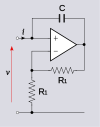
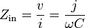
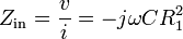
The negative of any impedance can be produced by a negative impedance converter (INIC in the examples below), including negative capacitance and negative inductance.[1] NIC can further be used to design floating impedances - like a floating negative inductor.[2][3]
  |
  |
  |
  |
See also
- Negative resistance
- Miller theorem applications
- Gyrator (which uses operational amplifier to implement an inductor with a capacitor)
References
- ↑ Chen, W.-K. (2003). The Circuits and Filters Handbook. CRC Press. pp. 396–397. ISBN 0-8493-0912-3.
- ↑ Mehrotra, S. R. (2005). "The Synthetic floating negative inductor using only two op-amps". Electronics World 111 (1827): 47.
- ↑ US patent 3493901, Deboo, G. J., "Gyrator type circuit", issued 1970-02-03, assigned to NASA