Magic eye tube

A magic eye indicator, called in technical literature an electron-ray indicator tube,[1] is a vacuum tube which gives a visual indication of the strength of an electronic signal, such as an audio output, radio-frequency signal strength, or other functions.[1] It is also called a cat's eye, or tuning eye in America. Its first broad application was as a tuning indicator in radio receivers, to give an indication of the relative strength of the received radio signal, to show when a radio station was properly tuned in.[1]
The eye tubes were developed as a cheaper alternative to the needle movement meters. It was not until the 1960s that needle meters were made economically enough in Japan to displace indicator tubes.[2] The tubes were used in vacuum tube receivers from around 1936 to 1980 before vacuum tubes were replaced by transistors in radios.[3] An earlier tuning aid which the Magic Eye replaced was the "Tuneon" neon lamp.[3][4]
History
The "magic eye" valve for tuning radio receivers was invented in 1932 by Allen B. DuMont (who spent most of the 1930s improving the lifetime of cathode ray tubes, and ultimately formed the DuMont Television Network).[5][6][7] It is a miniature cathode ray tube, usually with a built-in triode signal amplifier. It usually glows bright green, (occasionally yellow in some very old types, e.g., EM4) and the glowing ends grow to meet in the middle as the voltage on a control grid increases. It is used in a circuit that drives the grid with a voltage that changes with signal strength; as the tuning knob is turned, the gap in the eye becomes narrowest when a station is tuned in correctly.
The RCA 6E5 of 1935 was the first commercial tube.[8][9]
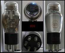
These devices were basically made in two forms – an end-viewed type usually with an octal or side-contact base, and a smaller side-viewed noval B9A based all-glass type. The round cone-shaped fluorescent screen together with the black cap that shielded the red light from the cathode/heater assembly was what prompted the contemporary advertisers to coin the term "Magic Eye", a term still used.
There was a miniature version with wire ends (Mullard DM70/DM71, Mazda 1M1/1M3, GEC/Marconi Y25) intended for battery operation, used in one Ever Ready AM/FM battery receiver with push-pull output, as well as a small number of AM/FM mains receivers, which lit the valve from the 6.3V heater supply via a 220-ohm resistor or from the audio output valve's cathode bias. It is more like a modern Vacuum fluorescent display than a CRT. One or two small reel-to-reel tape recorders also used the DM70/DM71 to indicate recording level, including a transistorised model with the valve lit from the bias-oscillator voltage.
Use in radios
The purpose of "magic-eyes" in radio sets is to help tune a station in; the visual aid of the tube makes variations in signal strength more obvious than by ear alone, because the automatic gain control (AGC) action tends to increase the audio volume of a mistuned station, so that the volume varies relatively little as the tuning knob is turned. The tuning eye was driven by the AGC voltage rather than the audio signal.
When, in the early 1950s, FM radio sets were made available on the UK market, many different types of magic eye were made available, with differing displays, but they all worked the same way. Some eyes had a separate small display to light up indicating a stereo signal on FM.
The device consists of a valve with two electrode assemblies, a triode amplifier and a display section consisting of a conical-shaped target anode coated with zinc-silicate or similar. The display section's anode was usually directly connected to the receiver's full + HT voltage, whilst the triode-anode was (usually internally) connected to a control electrode mounted between cathode and the target-anode, and externally connected to + HT via a high-value resistor, 1 megohm typically.
When the receiver is switched on but not tuned to a station, the target-anode glows green due to electrons striking it, with the exception of the area by the internal control-electrode. This electrode is typically 150-200V negative with respect to the target-anode, repelling electrons from the target in this region, causing a dark sector to appear on the display.
The control-grid of the triode-amplifier section is connected to a point where a negative control voltage dependent on signal strength is available, e. g. the AGC line in an AM superheterodyne receiver, or the limiter stage or FM detector in an FM receiver. As a station is tuned in the triode-grid becomes more negative with respect to the common cathode.
The British Leak company used an EM84 indicator as a very precise tuning-indicator in their Troughline FM tuner series, by mixing the AGC voltages from the two limiter valve grids at the indicator sensing-grid. By this means accurate tuning was indicated by a fully open sharp shadow, whilst off-tune the indicator produced a partially closed shadow.
Other applications
Magic eye tubes were used as the recording level indicator for tape recorders, and it is also possible to use them (in a specially adapted circuit) as a means of rough frequency comparison as a simpler alternative to Lissajous figures.
A magic eye tube is essentially an inexpensive uncalibrated (and not necessarily linear) voltage indicator, and can be used wherever an indication of voltage is needed, saving the cost of a more accurate calibrated meter.
At least one design of capacitance bridge used this type of tube to indicate that the bridge was balanced.
The function of a magic eye can be achieved with modern semiconductor circuitry and optoelectronic displays. The 100-volt-plus voltages required by magic eyes are not present in modern devices, so the magic eye is now obsolete.
The magic eye tube was also used on the cover of My Morning Jacket's 2011 album Circuital. The tube was shown as being almost fully lit.
See also
References
- ↑ 1.0 1.1 1.2 Spangenberg, Karl R. (1948). Vacuum Tubes. New York: McGraw-Hill Book Co. pp. 723–724.
- ↑ http://home.comcast.net/~jlrmsousa/precise_db_monitoring_with_eye_tubes_november_2006_audioxpress_joe_sousa2667.pdf
- ↑ 3.0 3.1 Erb, Ernest (July 27, 2009). "History of tuning indicators; meters, graphs, Magic Eye, LED". Radio History forum. RadioMuseum.com. Retrieved August 23, 2014.
- ↑ Radio Museum: Tuneon
- ↑ US 2098231, DuMont, Allen B., "Cathode ray device", published May 28, 1932, issued November 9, 1937
- ↑ US 2163256, DuMont, Allen B., "Cathode ray tube", published September 18, 1934, issued June 20, 1939
- ↑ David Weinstein, The Forgotten Network: DuMont and the Birth of American Television. Temple University Press, 2006, p.11
- ↑ Herbert M. Wagner of R.C.A. invented the familiar form of the "magic eye" tuning vacuum tube: US 2051189, Wagner, H. M., "Tuning indicator tube", published June 27, 1935, issued August 18, 1936
- ↑ Radio Museum: 6E5
External links
| Wikimedia Commons has media related to Magic-eye vacuum tubes. |
- A more technical description
- Gallery of eye-tubes by SM5CBW, some with animations
- Magic eye tubes in action and solid-state magic eye recreation
- Wealth of information on the magic eye
- Precise dB measurements with eye tubes
- How the DM70 operates
- Video demonstration and explanation
| ||||||||||||||||||||||||||||||||||
| ||||||||||||||||||