LM317
The LM317 is a popular adjustable linear voltage regulator. It was invented by Robert C. Dobkin and Robert J. Widlar in 1970[1][2] while they worked at National Semiconductor.
The LM337, a negative complement to the LM317, regulates voltages below, rather than above, the reference. It was designed by Robert "Bob" Pease.
Specifications
| Attribute | Value |
|---|---|
| Vout range | 1.25 V – 37 V |
| Vin – Vout difference | 3 V – 40 V |
| Operation ambient temperature | 0 °C – 125 °C |
| Output Imax | 1.5 A (with proper heat sinking) |
| Minimum Load Current | 3.5 mA typical, 12 mA maximum[3] |
Operation
As linear regulators, the LM317 and LM337 are used in DC to DC converter applications.
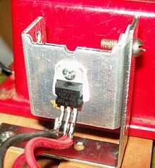
Linear regulators inherently draw as much current as they supply. When this current is multiplied by the voltage difference between input and output, a significant amount of heat results. Therefore the use of an LM317 commonly also requires a heat sink. For large voltage differences, the energy lost as heat can ultimately be greater than that provided by the circuit. This is the trade-off for using linear regulators which are a simple way to provide a stable voltage with few additional components. The alternative is to use a switching voltage regulator which is usually more efficient but has a larger footprint and requires a larger number of associated components.
In packages with a heat-dissipating mounting tab, such as TO-220, the tab is connected internally to the output pin which may make it necessary to electrically isolate the tab or the heat sink from other parts of the application circuit. Failure to do this may cause the circuit to short.
Voltage regulator
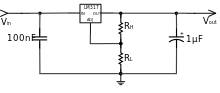
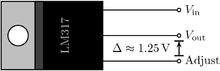
The LM317 has three pins: INput, OUTput, and ADJustment. The device is conceptually an op amp with a relatively high output current capacity. The inverting input of the amp is the adjustment pin, while the non-inverting input is set by an internal bandgap voltage reference which produces a stable reference voltage of 1.25 V.
A resistive voltage divider between the output and ground configures the op amp as a non-inverting amplifier so that the voltage of the output pin is continuously adjusted to be a fixed amount, the reference voltage, above that of the adjustment pin. Ideally, this makes the output voltage:
- Vout = Vref (1 + RL/RH)
Because some quiescent current flows from the adjustment pin of the device, an error term is added:
- Vout = Vref (1 + RL/RH) + IQRL
To make the output more stable, the device is designed to keep the quiescent current at or below 100µA, making it possible to ignore the error term in nearly all practical cases.[4]
Current regulator
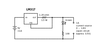
The device can be configured to regulate the current to a load, rather than the voltage, by replacing the low-side resistor of the divider with the load itself. The output current is that resulting from dropping the reference voltage across the resistor. Ideally, this is:
- Iout = Vref/RH
Accounting for quiescent current, this becomes:
- Iout = (Vref/RH) + IQ
LM317 can also be used to design various other circuits like 0 V to 30 V regulator circuit, adjustable regulator circuit with improved ripple rejection, precision current limiter circuit, tracking pre-regulator circuit, 1.25 V to 20 V regulator circuit with minimum program current, adjustable multiple on-card regulators with single control, battery charger circuit, 50 mA constant current battery charger circuit, slow turn-on 15 V regulator circuit, ac voltage regulator circuit, current-limited 6 V charger circuit, adjustable 4 V regulator circuit, high-current adjustable regulator circuit and many more. [5]
Compared to 78xx/79xx
The LM317 is an adjustable analogue to the popular 78xx fixed regulators. Like the LM317, each of the 78xx regulators is designed to adjust the output voltage until it is some fixed voltage above the adjustment pin (which in this case is labeled "ground").
The mechanism used is similar enough that a voltage divider can be used in the same way as with the LM317 and the output follows the same formula, using the regulator's fixed voltage for Vref (e.g. 5 V for 7805). However, the 78xx devices' quiescent current is substantially higher and less stable. Because of this, the error term in the formula cannot be ignored and the value of the low-side resistor becomes more critical.[6] More stable adjustments can be made by providing a reference voltage that is less sensitive than a resistive divider to current fluctuations, such as a diode drop or a voltage buffer. The LM317 is designed to compensate for these fluctuations internally, making such measures unnecessary.
The LM337 relates in the same way to the fixed 79xx regulators.
See also
References
- ↑ US patent 3617859, Robert C. Dobkin & Robert J. Widlar, "ELECTRICAL REGULATOR APPARATUS INCLUDING A ZERO TEMPERATURE COEFFICIENT VOLTAGE REFERENCE CIRCUIT", issued 1971-11-02, assigned to National Semiconductor Corporation
- ↑ "Electrical regulator apparatus including a zero temperature coefficient voltage reference circuit". Google Patents. Retrieved 31 March 2015.
- ↑ http://www.fairchildsemi.com/ds/LM/LM317.pdf
- ↑ "LM117/LM317A/LM317-N 3-Terminal Adjustable Regulator". 2004 May, Revised 2013 August. Retrieved 2013-10-02. Check date values in:
|date=(help) - ↑ "LM317 3-Terminal Adjustable Regulator". Texas Instruments. October 2014. pp. 11–16. Archived from the original on 31 March 2015. Retrieved 31 March 2015.
- ↑ "LM340-N/LM78XX Series 3-Terminal Positive Regulators". 2000 February, Revised 2013 March. Retrieved 2013-10-02. Check date values in:
|date=(help)
External links
- Band-Gap
- The Design of Band-Gap Reference Circuits: Trials and Tribulations – Robert Pease, National Semiconductor (shows LM317 design in Figure 4: LM117)
- LM317 Bandgap Voltage Reference Example (ECE 327) – Brief explanation of the temperature-independent bandgap reference circuit within the LM317.
- IC Datasheets
- Voltage Regulator Databook (Historical 1980), National Semiconductor
- LM317 (positive), LM350 (3 Amp), Texas Instruments (TI acquired National Semiconductor)
- LM317 (positive), LM350 (3 Amp), ON Semiconductor
- LM317 (positive), STMicroelectronics
- LM337 (negative), Texas Instruments