Geodetic datum
| Geodesy | ||||||||||||||||
|---|---|---|---|---|---|---|---|---|---|---|---|---|---|---|---|---|
| Fundamentals | ||||||||||||||||
| Concepts | ||||||||||||||||
| Technologies | ||||||||||||||||
| Standards | ||||||||||||||||
|
||||||||||||||||
| History | ||||||||||||||||
A Geodetic system or geodetic datum is a coordinate system, and a set of reference points, used to locate places on the Earth (or similar objects). The modern definition of sea level is actually defined precisely by the datum WGS 84 from 1984 onward. Other datums are defined for other areas or at other times; ED50 was defined in 1950 over Europe and differs from WGS 84 by a few hundred meters depending on where in Europe you look. Mars has no oceans and so no sea level, but at least two martian datums have been used to locate places there.
Datums are used in geodesy, navigation, and surveying by cartographers and satellite navigation systems to translate positions indicated on maps (paper or digital) to their real position on Earth. Each starts with an ellipsoid (stretched sphere), and then defines latitude, longitude and altitude coordinates. One or more locations on the earth's surface is chosen as an anchor. For instance, at Meades Ranch, Kansas USA, 12 miles (19 km) north of Lucas, in the middle of a field, there is a bronze surveyor's disk embedded in concrete that has a dot in the middle, which is defined as 39°13′26.71218″N 98°32′31.74604″W / 39.2240867167°N 98.5421516778°W,[1] in the NAD83 datum (very close to WGS 84).
The difference in co-ordinates between datums is commonly referred to as datum shift. The datum shift between two particular datums can vary from one place to another within one country or region, and can be anything from zero to hundreds of meters (or several kilometers for some remote islands). The North Pole, South Pole and Equator may be assumed to be in different positions on different datums, so True North may be very slightly different. Different datums use different estimates for the precise shape and size of the Earth (reference ellipsoids).
Because the Earth is an imperfect ellipsoid, localised datums can give a more accurate representation of the area of coverage than WGS 84. OSGB36, for example, is a better approximation to the geoid covering the British Isles than the global WGS 84 ellipsoid. However, as the benefits of a global system outweigh the greater accuracy, the global WGS 84 datum is becoming increasingly adopted.
Horizontal datums are used for describing a point on the Earth's surface, in latitude and longitude or another coordinate system. Vertical datums measure elevations or depths.
In engineering and drafting, a datum is a reference point, surface, or axis on an object against which measurements are made.

Datum
In surveying and geodesy, a datum is a reference point or surface against which position measurements are made, and an associated model of the shape of the earth for computing positions. Horizontal datums are used for describing a point on the earth's surface, in latitude and longitude or another coordinate system. Vertical datums are used to measure elevations or underwater depths.
Horizontal datum
The horizontal datum is the model used to measure positions on the earth. A specific point on the earth can have substantially different coordinates, depending on the datum used to make the measurement. There are hundreds of locally-developed horizontal datums around the world, usually referenced to some convenient local reference point. Contemporary datums, based on increasingly accurate measurements of the shape of the earth, are intended to cover larger areas. The WGS 84 datum, which is almost identical to the NAD83 datum used in North America and the ETRS89 datum used in Europe, is a common standard datum.
For example, in Sydney there is a 200 metres (700 feet) difference between GPS coordinates configured in GDA (based on global standard WGS84) and AGD (used for most local maps), which is an unacceptably large error for some applications, such as surveying or site location for scuba diving.[2]
Vertical datum

A vertical datum is used for measuring the elevations of points on the sea level. Vertical datums are either: tidal, based on sea levels; gravimetric, based on a geoid; or geodetic, based on the same ellipsoid models of the earth used for computing horizontal datums.
In common usage, elevations are often cited in height above sea level, although what “sea level” actually means is a more complex issue than might at first be thought: the height of the sea surface at any one place and time is a result of numerous effects, including waves, wind and currents, atmospheric pressure, tides, topography, and even differences in the strength of gravity due to the presence of mountains etc.
For the purpose of measuring the height of objects on land, the usual datum used is mean sea level (MSL). This is a tidal datum which is described as the arithmetic mean of the hourly water elevation taken over a specific 19 years cycle. This definition averages out tidal highs and lows (caused by the gravitational effects of the sun and the moon) and short term variations. It will not remove the effects of local gravity strength, and so the height of MSL, relative to a geodetic datum, will vary around the world, and even around one country. Countries tend to choose the mean sea level at one specific point to be used as the standard “sea level” for all mapping and surveying in that country. (For example, in Great Britain, the national vertical datum, Ordnance Datum Newlyn, is based on what was mean sea level at Newlyn in Cornwall between 1915 and 1921). However, zero elevation as defined by one country is not the same as zero elevation defined by another (because MSL is not the same everywhere), which is why locally defined vertical datums differ from one another.
A different principle is used when choosing a datum for nautical charts. For safety reasons, a mariner must be able to know the minimum depth of water that could occur at any point. For this reason, depths and tides on a nautical chart are measured relative to chart datum, which is defined to be a level below which tide rarely falls. Exactly how this is chosen depends on the tidal regime in the area being charted and on the policy of the hydrographic office producing the chart in question; a typical definition is Lowest Astronomical Tide (the lowest tide predictable from the effects of gravity), or Mean Lower Low Water (the average lowest tide of each day), although MSL is sometimes used in waters with very low tidal ranges.
Conversely, if a ship is to safely pass under a low bridge or overhead power cable, the mariner must know the minimum clearance between the masthead and the obstruction, which will occur at high tide. Consequently, bridge clearances etc. are given relative to a datum based on high tide, such as Highest Astronomical Tide or Mean High Water Springs.
Sea level does not remain constant throughout geological time, and so tidal datums are less useful when studying very long-term processes. In some situations sea level does not apply at all — for instance for mapping Mars' surface — forcing the use of a different "zero elevation", such as mean radius.
A geodetic vertical datum takes some specific zero point, and computes elevations based on the geodetic model being used, without further reference to sea levels. Usually, the starting reference point is a tide gauge, so at that point the geodetic and tidal datums might match, but due to sea level variations, the two scales may not match elsewhere. An example of a gravity-based geodetic datum is NAVD88, used in North America, which is referenced to a point in Quebec, Canada. Ellipsoid-based datums such as WGS84, GRS80 or NAD83 use a theoretical surface that may differ significantly from the geoid.
Geodetic coordinates

In geodetic coordinates the Earth's surface is approximated by an ellipsoid and locations near the surface are described in terms of latitude ( ), longitude (
 ) and height (
 ).[footnotes 1]
Geodetic versus geocentric latitude
It is important to note that geodetic latitude () (resp. altitude) is different from geocentric latitude ( ) (resp. altitude). Geodetic latitude is determined by the angle between the normal of the ellipsoid and the plane of the equator, whereas geocentric latitude is determined around the centre (see figure). Unless otherwise specified latitude is geodetic latitude.
Earth reference ellipsoid
Defining and derived parameters
The ellipsoid is completely parameterised by the semi-major axis  and the flattening
  .
.
| Parameter | Symbol |
|---|---|
| Semi-major axis | a |
| Reciprocal of flattening | 1/f |
From a and f it is possible to derive the semi-minor axis b, first eccentricity e and second eccentricity e′ of the ellipsoid
| Parameter | Value |
|---|---|
| semi-minor axis | b = a(1 − f) |
| First eccentricity squared | e2 = 1 − b2/a2 = 2f − f2 |
| Second eccentricity squared | e′2 = a2/b2 − 1 = f(2 − f)/(1 − f)2 |
Parameters for some geodetic systems
- Australian Geodetic Datum 1966 [AGD66] and Australian Geodetic Datum 1984 (AGD84)
AGD66 and AGD84 both use the parameters defined by Australian National Spheroid (see below)
- Australian National Spheroid (ANS)
| Parameter | Notation | Value |
|---|---|---|
| semi-major axis | a | 6 378 160.000 m |
| Reciprocal of Flattening | 1/f | 298.25 |
- Geocentric Datum of Australia 1994 (GDA94)
GDA94 uses the parameters defined by GRS80 (see below)
- Geodetic Reference System 1980 (GRS80)
| Parameter | Notation | Value |
|---|---|---|
| semi-major axis | a | 6 378 137 m |
| Reciprocal of flattening | 1/f | 298.257 222 101 |
see GDA Technical Manual document for more details; the value given above for the flattening is not exact.
- World Geodetic System 1984 (WGS84)
The Global Positioning System (GPS) uses the World Geodetic System 1984 (WGS84) to determine the location of a point near the surface of the Earth.
| Parameter | Notation | Value |
|---|---|---|
| semi-major axis | a | 6 378 137.0 m |
| Reciprocal of flattening | 1/f | 298.257 223 563 |
| Constant | Notation | Value |
|---|---|---|
| Semi-minor axis | b | 6 356 752.3142 m |
| First eccentricity squared | e2 | 6.694 379 990 14x10−3 |
| Second eccentricity squared | e′2 | 6.739 496 742 28x10−3 |
see The official World Geodetic System 1984 document for more details.
A more comprehensive list of geodetic systems can be found here
Other Earth-based coordinate systems
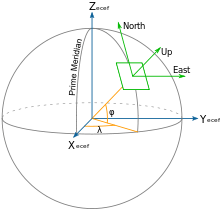
Earth-centered earth-fixed (ECEF or ECF) coordinates
The earth-centered earth-fixed (ECEF or ECF) or conventional terrestrial coordinate system rotates with the Earth and has its origin at the centre of the Earth. The  axis passes through the equator at the prime meridian. The
  axis passes through the north pole but it does not exactly coincide with the instantaneous Earth rotational axis.[3] The
  axis can be determined by the right-hand rule to be passing through the equator at 90° longitude.
Local east, north, up (ENU) coordinates
In many targeting and tracking applications the local East, North, Up (ENU) Cartesian coordinate system is far more intuitive and practical than ECEF or Geodetic coordinates. The local ENU coordinates are formed from a plane tangent to the Earth's surface fixed to a specific location and hence it is sometimes known as a "Local Tangent" or "local geodetic" plane. By convention the east axis is labeled  , the north
  and the up
  .
.
Local north, east, down (NED) coordinates
In an airplane most objects of interest are below you, so it is sensible to define down as a positive number. The North, East, Down (NED) coordinates allow you to do this as an alternative to the ENU local tangent plane. By convention the north axis is labeled  , the east
  and the down
  . To avoid confusion between and , etc. in this web page we will restrict the local coordinate frame to ENU.
Conversion calculations
Datum conversion is the process of converting the coordinates of a point from one datum system to another. Datum conversion may frequently be accompanied by a change of grid projection.
Geodetic to/from ECEF coordinates
From geodetic to ECEF

 ). The length IQ is equal to
  . R =
. R =  . The length PR is equal to
  .
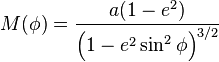
.Geodetic coordinates (latitude , longitude , height ) can be converted into ECEF coordinates using the
following formulae:
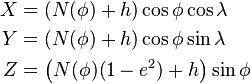
where
and  are the semi-major axis and the first numerical eccentricity of the ellipsoid respectively.
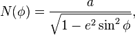
is called the Normal and is the distance from the surface to the Z-axis along the ellipsoid normal (see "Radius of curvature on the Earth"). The following equation holds:

where 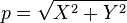 .
.
The orthogonality of the coordinates is confirmed via differentiation:
where
(see also "Meridian arc on the ellipsoid").
From ECEF to geodetic
The conversion of ECEF coordinates to geodetic coordinates (such WGS84) involves a little more trigonometry but is sensitive to small accuracy due to Rn and h being maybe 10^6 apart,[4][5] but longitude is same as geocentric,  .
.
There are several methods that solve the equation, two are shown.
Newton–Raphson method
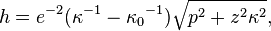
The following Bowring's irrational geodetic-latitude equation[6] is efficient to be solved by Newton–Raphson iteration method:[7]
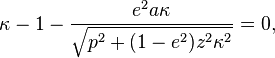
where  . The height is calculated as follows:
The iteration can be transformed into the following calculation:
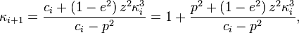
where 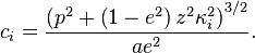
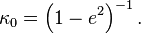
 is a good starter for the iteration when
  . Bowring showed that the single iteration produces the sufficiently accurate solution. He used extra trigonometric functions in his original formulation.
Ferrari's solution
The following[8] [9] solve the above equation:
![\begin{align}
\zeta &= (1 - e^2) z^2 / a^2 ,\\[6pt]
\rho &= (p^2 / a^2 + \zeta - e^4) / 6 ,\\[6pt]
s &= e^4 \zeta p^2 / ( 4 a^2) ,\\[6pt]
t &= \sqrt[3]{\rho^3 + s + \sqrt{s (s + 2 \rho^3)}} ,\\[6pt]
u &= \rho + t + \rho^2 / t ,\\[6pt]
v &= \sqrt{u^2 + e^4 \zeta} ,\\[6pt]
w &= e^2 (u + v - \zeta) / (2 v) ,\\[6pt]
\kappa &= 1 + e^2 (\sqrt{u + v + w^2} + w) / (u + v).
\end{align}](../I/m/ff94a4b38e10c9036764fbfa134cb38a.png)
Geodetic to/from ENU coordinates
To convert from geodetic coordinates to local ENU coordinates is a two-stage process
- Convert geodetic coordinates to ECEF coordinates
- Convert ECEF coordinates to local ENU coordinates
To convert from local ENU coordinates to geodetic coordinates is a two-stage process
- Convert local ENU coordinates to ECEF coordinates
- Convert ECEF coordinates to geodetic coordinates
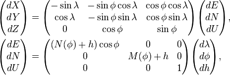
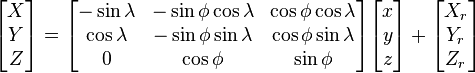
From ECEF to ENU
To transform from ECEF coordinates to the local coordinates we need a local reference point, typically this might be the location of a radar. If a radar is located at  and an aircraft at
  then the vector pointing from the radar to the aircraft in the ENU frame is
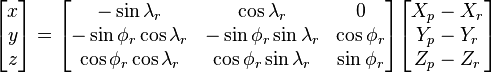
Note: is the geodetic latitude. A prior version of this page showed use of the geocentric latitude (). The geocentric latitude is not the appropriate up direction for the local tangent plane. If the original geodetic latitude is available it should be used, otherwise, the relationship between geodetic and geocentric latitude has an altitude dependency, and is captured by:

Obtaining geodetic latitude from geocentric coordinates from this relationship requires an iterative solution approach, otherwise the geodetic coordinates may be computed via the approach in the section above labeled "From ECEF to geodetic coordinates."
The geocentric and geodetic longitude have the same value. This is true for the Earth and other similar shaped planets because their latitude lines (parallels) can be considered in much more degree perfect circles when compared to their longitude lines (meridians).

Note: Unambiguous determination of and requires knowledge of which quadrant the coordinates lie in.
From ENU to ECEF
This is just the inversion of the ECEF to ENU transformation so
Reference datums
A reference datum is a known and constant surface which is used to describe the location of unknown points on the earth. Since reference datums can have different radii and different center points, a specific point on the earth can have substantially different coordinates depending on the datum used to make the measurement. There are hundreds of locally-developed reference datums around the world, usually referenced to some convenient local reference point. Contemporary datums, based on increasingly accurate measurements of the shape of the earth, are intended to cover larger areas. The most common reference Datums in use in North America are NAD27, NAD83, and WGS84.
The North American Datum of 1927 (NAD 27) is "the horizontal control datum for the United States that was defined by a location and azimuth on the Clarke spheroid of 1866, with origin at (the survey station) Meades Ranch (Kansas)." ... The geoidal height at Meades Ranch was assumed to be zero. "Geodetic positions on the North American Datum of 1927 were derived from the (coordinates of and an azimuth at Meades Ranch) through a readjustment of the triangulation of the entire network in which Laplace azimuths were introduced, and the Bowie method was used." (http://www.ngs.noaa.gov/faq.shtml#WhatDatum ) NAD27 is a local referencing system covering North America.
The North American Datum of 1983 (NAD 83) is "The horizontal control datum for the United States, Canada, Mexico, and Central America, based on a geocentric origin and the Geodetic Reference System 1980 (GRS80). "This datum, designated as NAD 83 ...is based on the adjustment of 250,000 points including 600 satellite Doppler stations which constrain the system to a geocentric origin." NAD83 may be considered a local referencing system.
WGS 84 is the World Geodetic System of 1984. It is the reference frame used by the U.S. Department of Defense (DoD) and is defined by the National Geospatial-Intelligence Agency (NGA) (formerly the Defense Mapping Agency, then the National Imagery and Mapping Agency). WGS 84 is used by DoD for all its mapping, charting, surveying, and navigation needs, including its GPS "broadcast" and "precise" orbits. WGS 84 was defined in January 1987 using Doppler satellite surveying techniques. It was used as the reference frame for broadcast GPS Ephemerides (orbits) beginning January 23, 1987. At 0000 GMT January 2, 1994, WGS 84 was upgraded in accuracy using GPS measurements. The formal name then became WGS 84 (G730), since the upgrade date coincided with the start of GPS Week 730. It became the reference frame for broadcast orbits on June 28, 1994. At 0000 GMT September 30, 1996 (the start of GPS Week 873), WGS 84 was redefined again and was more closely aligned with International Earth Rotation Service (IERS) frame ITRF 94. It is now formally called WGS 84 (G873). WGS 84 (G873) was adopted as the reference frame for broadcast orbits on January 29, 1997.[10]
The WGS84 datum, which is almost identical to the NAD83 datum used in North America, is the only world referencing system in place today. WGS84 is the default standard datum for coordinates stored in recreational and commercial GPS units.
Users of GPS are cautioned that they must always check the datum of the maps they are using. To correctly enter, display, and to store map related map coordinates, the datum of the map must be entered into the GPS map datum field.
Engineering datums
An engineering datum used in geometric dimensioning and tolerancing is a feature on an object used to create a reference system for measurement.[11]
Examples
Examples of map datums are:
- WGS 84, 72, 64 and 60 of the World Geodetic System
- NAD83, the North American Datum which is very similar to WGS84
- NAD27, the older North American Datum, of which NAD83 was basically a readjustment
- OSGB36 of the Ordnance Survey of Great Britain
- ED50, the European Datum
- Hong Kong Principal Datum, is 1.23m below the mean of 19 years (1965–83) observations of tide levels at North Point, Victoria Harbour.[12][13]
See also
- Axes conventions
- Geographic coordinate conversion
- Shape of the Earth
- Ordnance Datum
- World Geodetic System
Footnotes
- ↑ About the right/left-handed order of the coordinates, i.e.,
 or
or  , see Spherical coordinate system#Conventions.
References
- ↑ Meades Ranch Reset, NGS Data Sheet
- ↑ McFadyen, GPS and Diving
- ↑ Note on the BIRD ACS Reference Frames
- ↑ R. Burtch, A Comparison of Methods Used in Rectangular to Geodetic Coordinate Transformations.
- ↑ Featherstone, W. E.; Claessens, S. J. (2008). "Closed-Form Transformation between Geodetic and Ellipsoidal Coordinates". Stud. Geophys. Geod. 52 (1): 1–18. doi:10.1007/s11200-008-0002-6.
- ↑ Bowring, B. R. (1976). "Transformation from Spatial to Geographical Coordinates". Surv. Rev. 23 (181): 323–327. doi:10.1179/003962676791280626.
- ↑ Fukushima, T. (1999). "Fast Transform from Geocentric to Geodetic Coordinates". J. Geod. 73 (11): 603–610. doi:10.1007/s001900050271. (Appendix B)
- ↑ Vermeille, H., H. (2002). "Direct Transformation from Geocentric to Geodetic Coordinates". J. Geod. 76 (8): 451–454. doi:10.1007/s00190-002-0273-6.
- ↑ Gonzalez-Vega, Laureano; PoloBlanco, Irene (2009). "A symbolic analysis of Vermeille and Borkowski polynomials for transforming 3D Cartesian to geodetic coordinates". J. Geod 83 (11): 1071–1081. doi:10.1007/s00190-009-0325-2.
- ↑ WGS84 on the site of National Geodetic Survey
- ↑ ANSI Y14.5M (ISBN 0-7918-2223-0) for engineering datums.
- ↑ "Vertical Datum used in China - Hong Kong – onshore".
- ↑ Survey & Mapping Office | 測繪處
Further reading
- List of geodetic parameters for many systems from University of Colorado
- Gaposchkin, E. M. and Kołaczek, Barbara (1981) Reference Coordinate Systems for Earth Dynamics Taylor & Francis ISBN 9789027712608
- Kaplan, Understanding GPS: principles and applications, 1 ed. Norwood, MA 02062, USA: Artech House, Inc, 1996.
- GPS Notes
- Introduction to GPS Applications
- P. Misra and P. Enge, Global Positioning System Signals, Measurements, and Performance. Lincoln, Massachusetts: Ganga-Jamuna Press, 2001.
- Peter H. Dana: Geodetic Datum Overview – Large amount of technical information and discussion.
- UK Ordnance Survey
- US National Geodetic Survey
External links
| Look up datum in Wiktionary, the free dictionary. |
- GeographicLib includes a utility CartConvert which converts between geodetic and geocentric (ECEF) or local Cartesian (ENU) coordinates. This provides accurate results for all inputs including points close to the center of the earth.
- A collection of geodetic functions that solve a variety of problems in geodesy in Matlab.
- UK Ordnance Survey
- US National Geodetic Survey
- NGS FAQ – What is a geodetic datum?
- Convert coordinates between different datums
- About the surface of the Earth on kartoweb.itc.nl